Thanks for verifying this. I’m now reminded of another strange thing that has happened to me 2 or maybe 3 times over the last year or so. The first time was printing a 129-step target which resulted in an unexpectedly dark Pd print. The neg looked fine until I put it on a light table and saw clearly that the black perimeter and step 1 weren’t the solid black I had learned to expect with PiezoDN. I believe that for some unknown reason the K channel didn’t print at all. I ran a nozzle check which was perfect and ran another negative which printed perfectly. I never found the cause of the glitch and may not have even mentioned it to Walker. There was at least one other occasion when this happened and it was with a real negative. Again, I didn’t notice anything was wrong until I made a print. Since I don’t print a black masking edge there was no give-away clue that black ink was missing, but I remade the negative and the difference was visible side-by-side and of course in the print. This may be a long-shot here, but I want to make note of it as a possibility.
Hopefully Walker will see this and advise. I don’t really know, but since you have an extra cart I think it’s a good idea to use it.
Testing … my last reply is not showing up … dammit
Well that worked … hmmmmmm
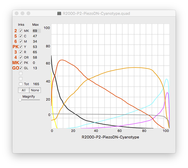
Is “Piezography P2” of this the chart what you used for ink placement? I’m asking because I don’t see ink placement for P2 in the P400/R2000, so I’m confused looking at the CurveViews about what is what.
[attachment file=30193]
I always run a nozzle check immediately before printing a negative. I figure the chances of the nozzle check being good and the print being bad are miniscule. Something else to worry about!
John, I have a suggestion or 2 at this point. First I do not use GO on the negatives in our shared dry environment. Consider duplicating your master curve, then opening your master curve copy.quad in a simple Text format - not sure what that is in Windows. Copy Yellow which is all zeros and paste that over the GL list of information that starts with 9000. You have now created a .quad without GO. Also, I checked the R2000 PiezoDN Cyanotype curve against another 8 channel printer curve I have. They are identical. Mix all your chemicals with distilled water. Be precise in the darkroom, which I know you are. Start over.
Hi Don,
I understand your instructions for eliminating GO. Thanks! But I am no longer working in a dry environment. Since I installed a humidifier, I have been keeping my “dim room” at 45% (doing it for the sake of the printer). I’m sitting in it now. It feels downright tropical.
Elsewhere in this discussion, Keith Schreiber suggested that humidity may actually be causing problems. For example, I may need to let my paper dry longer than the 1hr I have been allowing before exposing it.
But I suspect there’s something fundamental (not darkroom-related) that I’m doing wrong.
Which leads me to this question: Which curve should I be using as the “master” when I print the initial target for linearization? I have been using this one:
- R2000-P2-PiezoDN-Cyanotype.quad
Should I instead be using this one?
- R2000-P2-PiezoDN-Master.quad
I think I’ve said this several times on this forum and others related to choosing the starting curve but this answer should suffice for all such questions:
Use the curve that gets you the closest as your starting curve.
So, if you are printing cyanotype, use the cyanotype curve to start with. If you are printing Salt use the Salt curve to start with, etc.
best,
Walker
I thought so. Thanks for verifying! I am looking for reasons why my linearized curve is actually worse than the base cyanotype curve, which I have indeed been starting with. People in this discussion and elsewhere have mentioned the “master curve” in the context of linearization, and I began to wonder if they meant the curve with “Master” in its filename.
Hey Don - What’s your rationale for not using GO? I’m making my actual negatives on a 1430 so I’m not using it, but I have found them to be a wee bit fragile and have thought it would be good as a protective layer. If my 3880 is ever capable of making decent negs I was hoping they would be more robust with the GO being used.
PS - hoping to see you on Paella night next month.
Walker - That might be more self-explanatory to new users if the curves were named something like Cyan-Master, etc. to indicate that they are intended as the starting point for those processes. I think people see the name and think they are already linearized, without understanding that linearization is something that always should be done due to the inevitable personal variables.
Keith, I tried coating with GO and in my 14-20% humidity studio it actually flaked off in places. My negs are pretty resilient but I do let them air dry in a drawer overnight. In the morning I can no longer rub off the Matte Black which I have set to print for paperwhite only. Part of my solution to the long conversation we had before.
I would add for John, try backing off exposure 10% and just see what happens. It would be worth coating a number of sheets (potassium ferricyanide is cheap). and questioning everything you know. One negative will do it all and give you a control for your experimenting.
You are correct, something seems wrong and with everyone teleporting to try and solve it no one is actually looking over your shoulder to spot that one thing you don’t even know to mention.
John - Sorry if I contributed to the confusion about the starting curve. I did name one of my CurveView screenshots Cyan-Master, but it referred to the IJM supplied Cyanotype curve, not to the Master curve.
I too always run a nozzle check before each negative, and I did so before and after the one I mentioned where the K channel didn’t print at all. Both were perfect. I still have no idea what happened in those cases and am just grateful it has happened only 2 or 3 times.
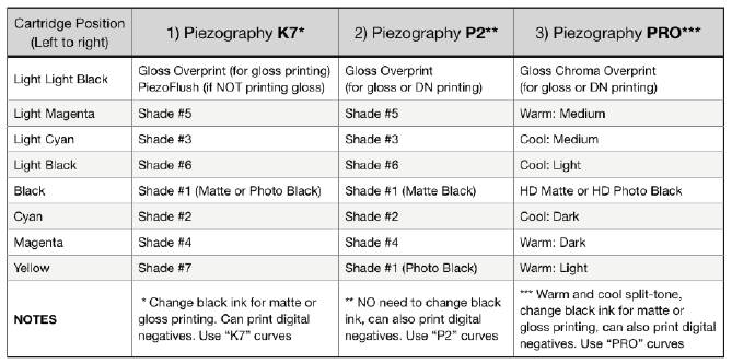
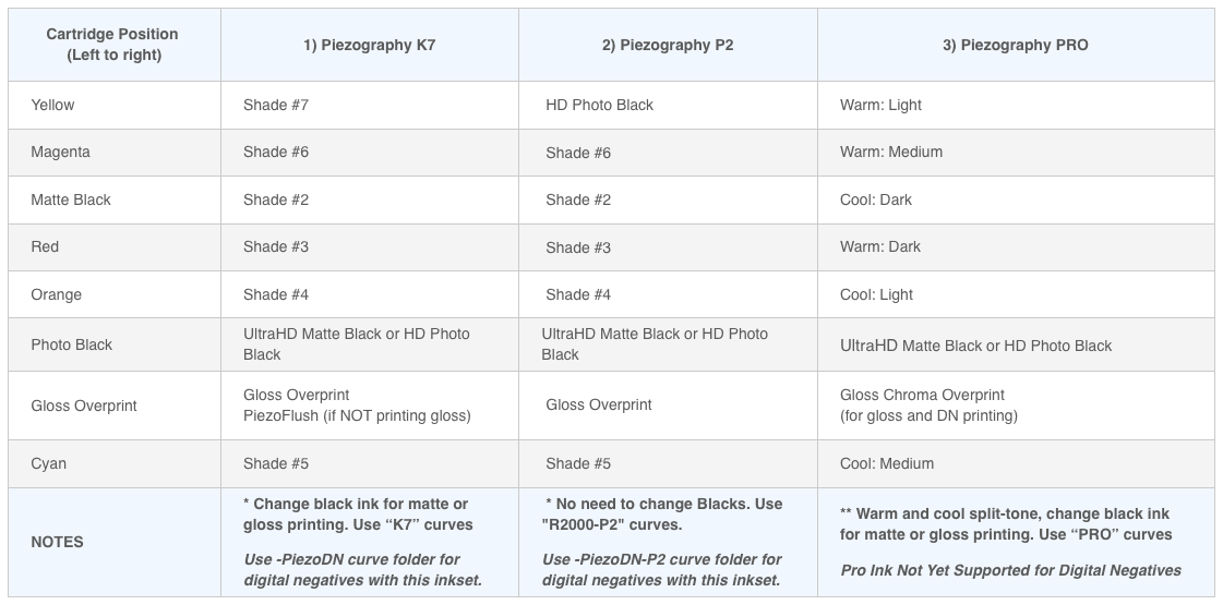
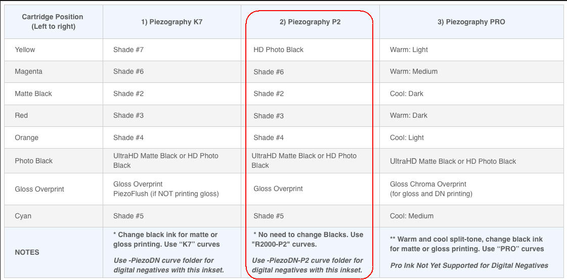
Back to the question about ink positions. You are using the P2 setup on your P400, but I can’t find a document that shows what that is. The document titled Insert #106, which is what is linked to from the P400 ink page on the store website, and which probably came with your inks and cartridges too, is where I got the chart that I posted. It does not show P2 ink positions for the P400/R2000. I did find this chart in a document on the Piezography Support Knowledge Base page:
[attachment file=30207]
I’m guessing this must be what you used. Is this correct?
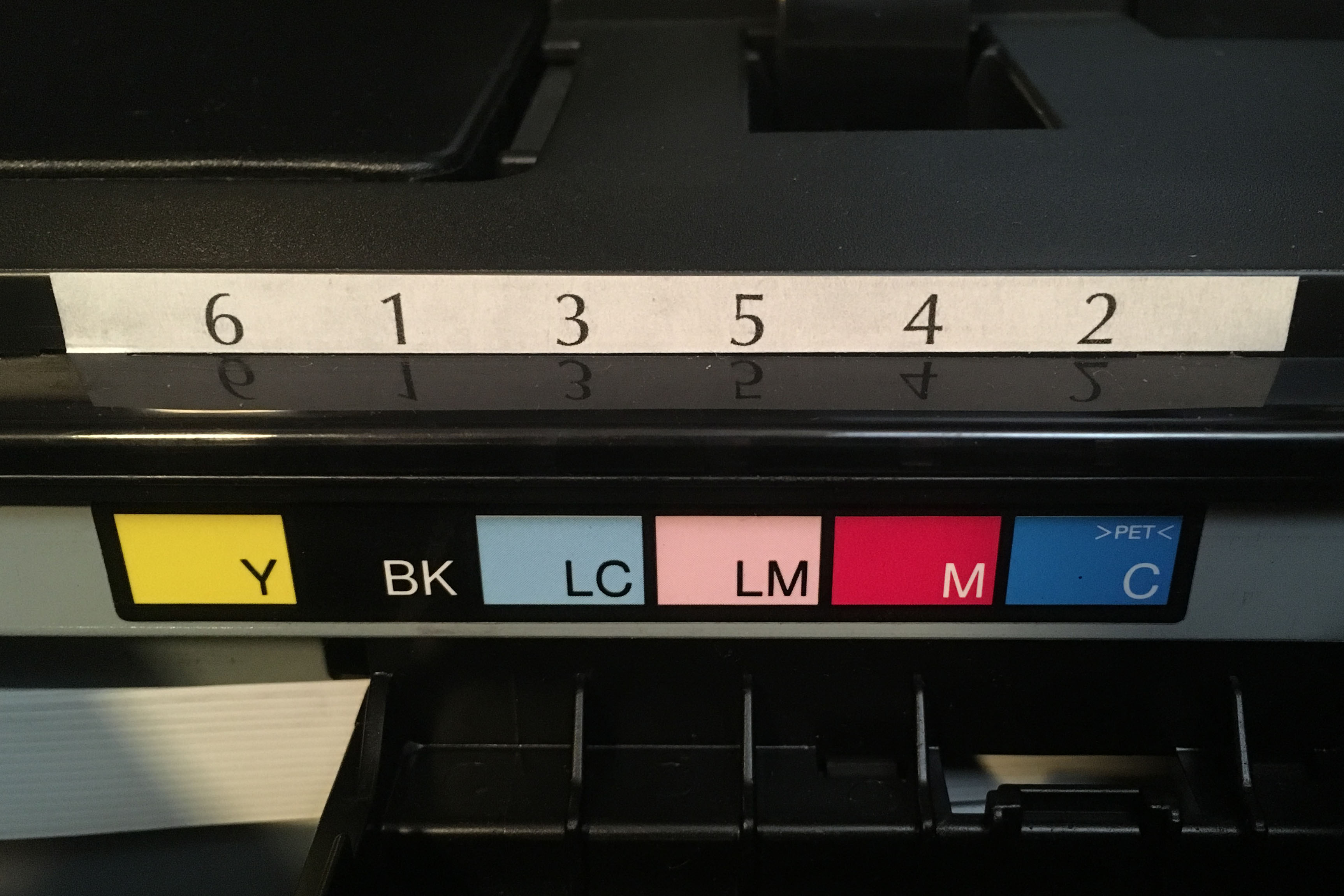
Here is an annotated CurveView of the Cyanotype (Master) curve correlating ink position to ink shade:
[attachment file=30208]
I got the positions from the bottom table on p. 3 of Insert# 106 (see attachment). I pointed out to Walker that the table is missing a heading. The heading should list the P400 (see attachment). The tables are confusing.
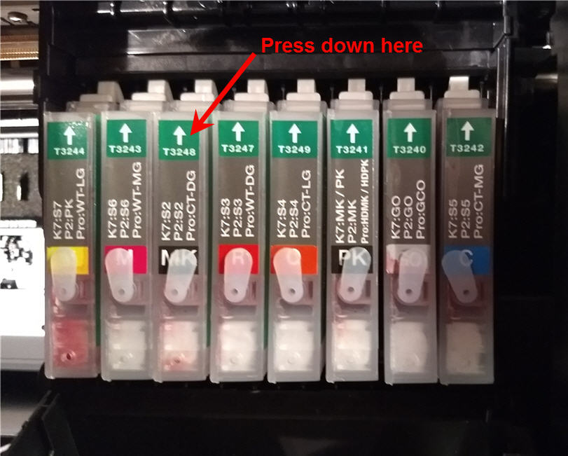
Here’s a shot of the carts, as installed, from an earlier post (attachment 2 - ignore the red arrow).
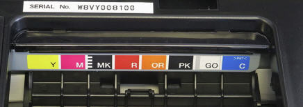
The IJM carts are keyed to the colors on the Epson printer (attachment 3), so you only have to match them up. It would be hard to make a mistake.
Thank you and Walker both for clarifying “Master”.
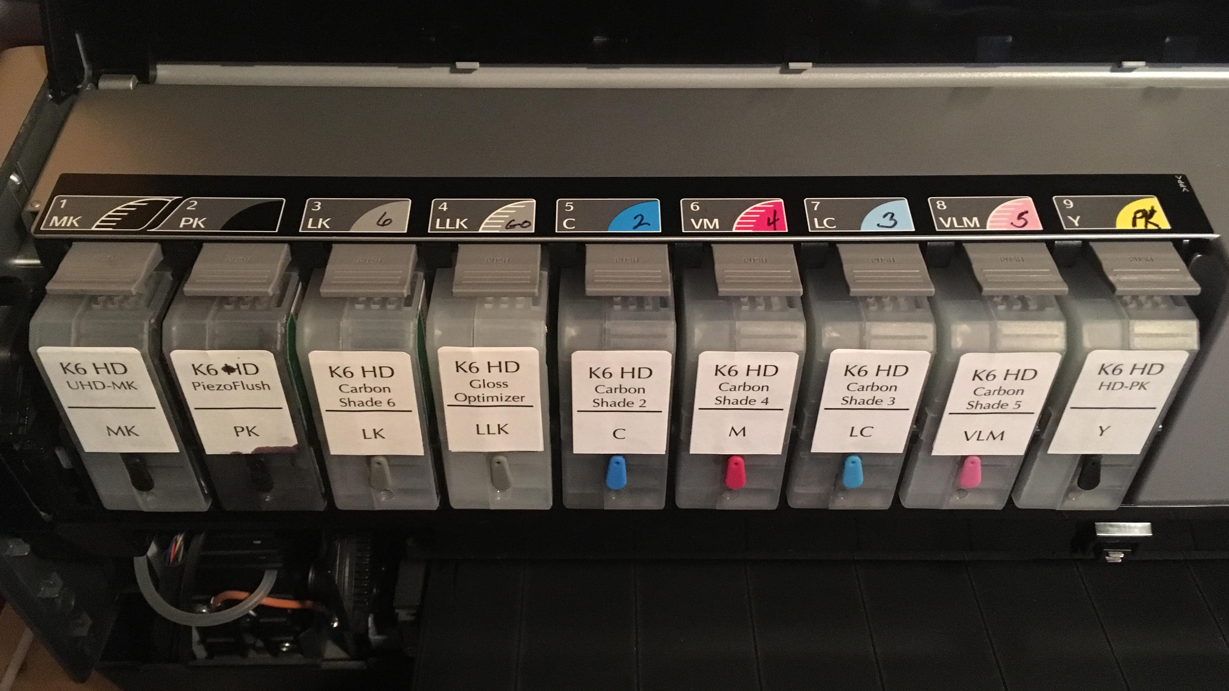
That’s wacky! The first ink placement chart that I posted was downloaded from the link on the P400 reusable cart page. It has the UC3 ink positions rather than whatever the P400 inks are called. That’s why I was confused. It’s not the same as what you posted, which is the same as the second one I posted. Anyhow, it looks like you are set up correctly. FWIW, I make another set of labels that I put on either the carts or the printer itself (like your 3rd pic), or both, with the actual Piezo inks that go in the carts. It has kept me from making stupid mistakes more than once.
[attachment file=30216]
[attachment file=30217]
Earlier I couldn’t post, now I get a double post. Sorry - there doesn’t seem to be a delete button.
Today I began another linearization, starting from the very beginning. This time I will carefully control my darkroom variables: allow negatives to cure for 24h, allow prints to sit fo 24h before measuring with spectro, and so-on. I’ll post again when I have results. Thanks again Keith and Walker for your help and encouragement.
Today I’m repeating the linearization of the cyanotype base curve. Once again, when I run QTR-Linearize-Quad.exe, the linearized quad file (-lin.quad) does not show up, but the CGCATS-out.txt appears immediately. The last time this happened, it took a while to show up, but I must have done something that I can’t remember. Today I waited for well over an hour and even rebooted my computer, but still no -lin.quad.
I found the problem: QTR-Linearize-Quad.exe assumes it is being run out of the QuadToneRIP/EyeOne directory. The program is clearly using paths relative to that directory to access whatever it needs to do its job. For convenience, I had copied the program into another folder together with its two input files and tried to run it from there. I learned something today!
On Mac the new files are always created in the same folder as the source files which must be in the same folder. You can then move the new quad to the correct location for installation. I’m afraid I have no idea how that is handled in Windows. But you seem to have figured it out. By the way, it’s CGATS, not CGCATS.