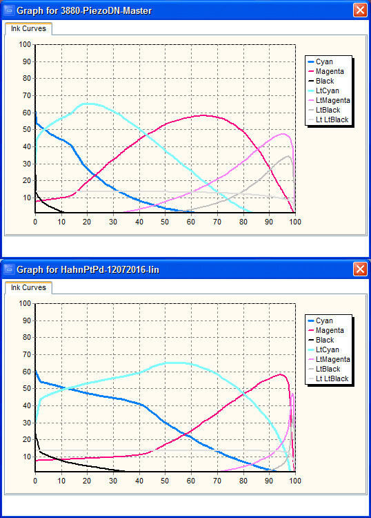
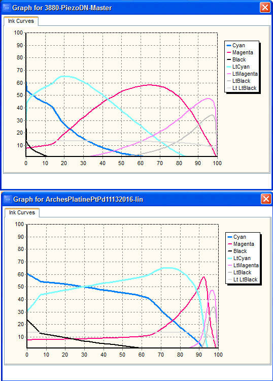
In doing a set of linearizations, the shape of the curves has changed dramatically from the master curves. The curves for the lighter inks are being pushed to the right. See image below. Is this a problem?
This indicates a requirement for massively dense negative. What process are you doing?
best,
Walker
The process is Pt/Pd. Do you think there is a problem with the curve?
Please post a picture of the target print that you measured along with a text file of the measurements. Have you made a verification test with that curve yet?
Also, the details of your printing method would be useful - paper, coating mixture, any additives, lightsource, exposure time, developer.
I made a verification print, and it is pretty much linear. I am just wondering if there is a problem with the lighter shades being pushed to the right.
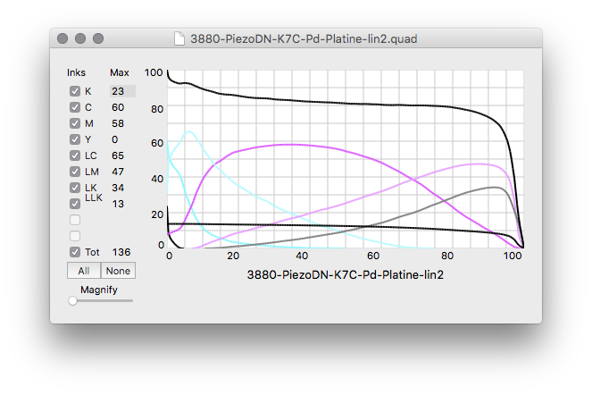
If you are happy with the result, maybe it is nothing to worry about. I had never looked at it in CurveView before, but here is my final Platine curve for comparison. Straight palladium with 1 drop 1.25% Na2 and 2 drops Tween20 per 2ml solution, developed in PO, fluorescent BL bulbs.
[attachment file=25842]
My curve is so far different from the master curve, that it has me a little worried.
I remember reading Jon saying that Piezography curves are superior because of overlapping ink shades and the use of trailing edge structure in each curve to fill in the spaces between dots in darker inks. He also said the curves uses as little as possible dark ink in a lighter shade to make dots invisible. With the drastic changes from the master curve, I fear these characteristics are no longer there. Maybe this is not as important with PiezoDN?
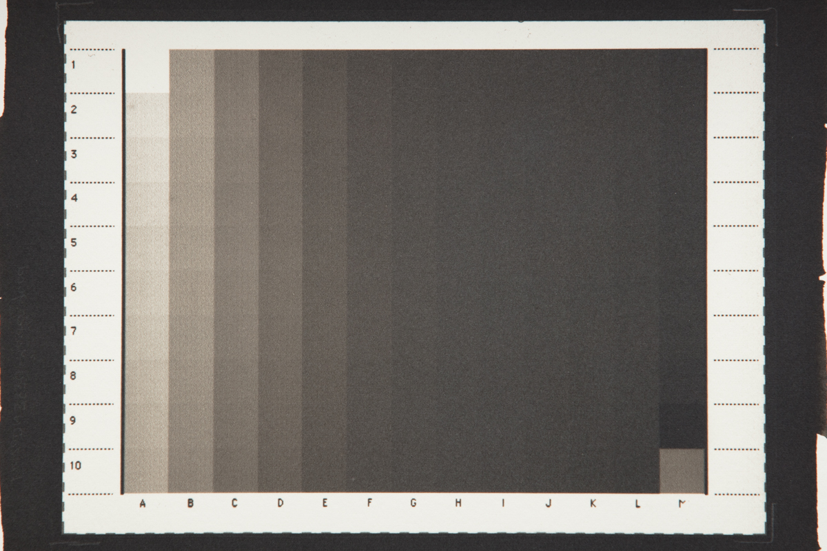
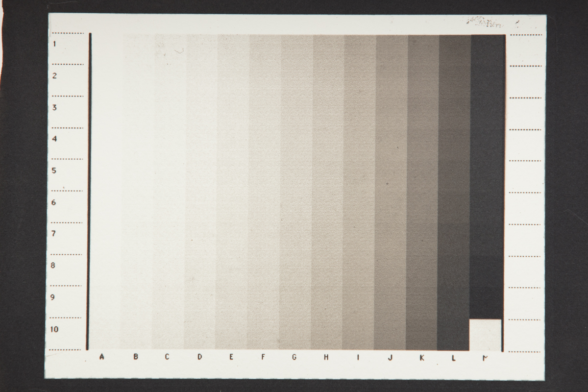
It would be really helpful if we could see what you are talking about. I don’t mean the Curve View. Please post pictures of the print of your master.quad neg which you measured to make the -lin.quad, and a picture of the print made from the -lin.quad negative. A phone pic is fine - they don’t need to be reproduction quality. And please post the text files of your measurements. I’d like to try to recreate this and see if I get the same result.
Hi Keith,
Attached are pictures of the prints made from the master quad file (3880-PiezoDN-Master.quad) and the print made from the first round of linearization. Also attached is an image comparing the master quad curve and the -lin curve from the first round of linearization.
The .txt file is the quad file created from the first linearization. I used a smoothing factor of 2 to generate it. I changed the extension of the file in order to do the upload.
The text files of the measurements will be in the next post since I seem to be limited to 4 attachments.
ArchesPlatinePtPd11132016-lin-quad.txt (10.2 KB)
Here are the two measurement files. PiezoDN-129step-i1Pro2-ArchesPtPd11122016.txt is the measurement file from the master. PiezoDN-129step-i1Pro2-ArchesPtPd11152016.txt is from the -lin file.
Something is very very off with your printer.
Please confirm which ink shades you put in which slots.
-Walker
Walker,
What are you seeing that makes you think that something is very off with the printer?
I have re-checked that I do have the correct inks in the correct slots.
Also, are you printing at 2880dpi and UniDirectional?
There are major lines in the image. If you were printing at 720dpi this would both drastically decrease the density of the neg and create lines.
It’s very hard to debug this from afar.
-Walker
Yes, we are printing at 2880 dpi and UniDirectional.
The lines in the image were due to improper head alignment, which has been fixed after these prints.
I don’t believe this was contributing to the curves being pushed to the right, which is my original question.
By the way, we were able to linearize the curve, but I’m concerned about how the curves are being pushed to the right.
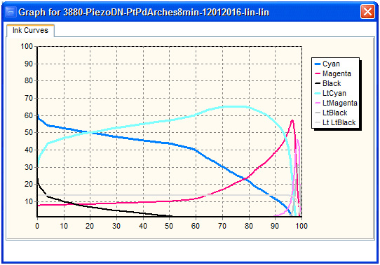
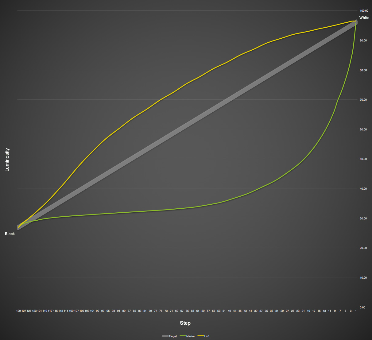
Looking at the test images, your master looks way overexposed, and the -lin print looks way overcorrected, probably because the Master is out of the ballpark. Here is a graph showing them together. Do I remember right that you remade the limits of the Master? If so, you didn’t do it right. If not, I think you should.
[attachment file=25862]
Hi Keith,
You may be thinking about my previous post regarding a ziatype process where I used a different master quad file with an increased density. You have a good memory.
For this one, I used the original master curve.
I did notice that it looks overexposed. I used a stouffer wedge to determine the base exposure, and could see that the steps were very close in darkness, but there were still differences between the steps, especially if I measured them.
When you determine the base exposure using a stouffer wedge, do you eyeball it or do you measure?
If I went with a shorter exposure time, it would lead to a lower dmax, correct?
In the end, we did get it linearized, but are concerned with how the curve looks. Are there other issues I should be concerned about?
Yes, that was it - Ziatype. Thanks for clarifying that.
Once you determined that base exposure did you back off by 1/3 - 1/2 stop? I’ve written at length about this before and don’t have time to rewrite it right now. You also should verify it with a digital 21- or 31-step wedge on Pictorico before committing to your calculated time since the base densities differ. Calculations are great but we still need to verify the results empirically! Very briefly, print the Stouffer scale until steps 1 and 2 merge. Judging it by eye is fine. That proves that you have gone past the time needed to reach Dmax by 1/2 stop with a 21-step or 1/3 stop on a 31-step. But since you don’t want them to merge in a real print, you need to reduce the time that you used by 1/2 stop or 1/3 stop accordingly. Then you also need to account for the difference in base density. According to my measurements Pictorico is about 0.07 denser (~1/4 stop) than the Stouffer film base, so the final correction will be more like 1/3 to 1/4 stop less. As an example, if it takes 10 minutes to merge steps 1 and 2 with a 21-step, reduce it by 1/3 stop to get ~ 8:30. There is a formula for this that uses fractional square roots or something like that. I’ll post it if I can find it.
Looking at the green line in the graph I posted above, I wouldn’t be surprised if you are a full stop or more overexposed. I also think that is exactly why your ink usage as shown in the CurveView is the way it is. You are having to put an excessive amount of ink into the shadows to compensate for gross overexposure.
Try cutting exposure time in half.
Thanks Keith, I’ll re-do the target at a reduce exposure time and report back.