Art asked how I came up with the adjusted Master curve for the peculiar response with Metal Halide exposure light that I suggested Gilles try.
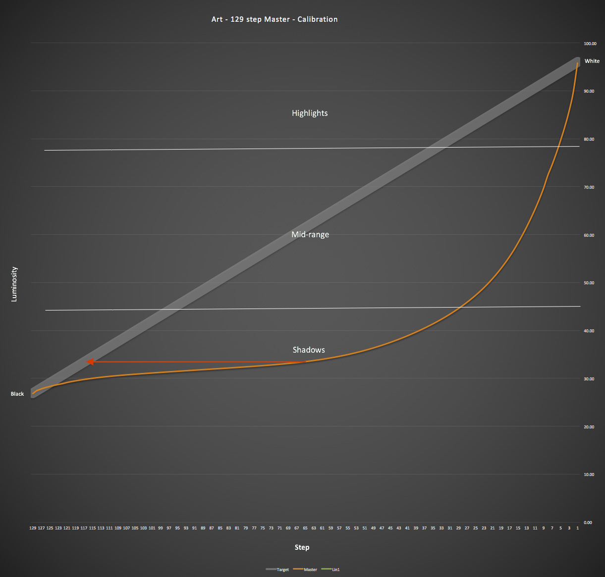
First I looked at the curve of the initial Master target print and analyzed it. I divided it into highlights, mid-range, and shadows. I set the divisions somewhat arbitrarily at 25% and 75% which are represented by the horizontal white lines added to the graph. The horizontal axis of the graph, which represents the steps of the 129-step target, can also be thought of as ink density. You can see that much more ink is needed to block the light and bring the Pd (in this case) response up to linear. The shadow region, especially the lower half of the shadow region, has very little separation between adjacent tones. So I need a curve adjustment that will correct for this. It does not need to be perfect - that is the job of the Linearization process that we do with the Smoother tool - just close enough to not overload the Smoother.
[attachment file=26248]
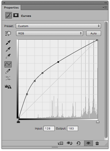
For this process I used the Curve Adjustment Tool. First I made a model, in a Photoshop Curve window, of what I wanted to accomplish based on what I think is the most critical part, the shadow region. I selected a point on the curve where the toe begins and drew a horizontal line, represented by the red arrow, left to where it intersects the linear Target line. This will be my first control point on the adjustment curve. Experience tells me not to overdo the correction curve, so I don’t make it quite as dramatic as it look like it might need to be. From there I use the remaining 3 control points to bend the rest of the curve to approximate a mirror image of the Master. I am not concerned with making it perfect, since anything above the line is going to be an improvement, but I want it to be reasonably close and I want it to be smooth.
[attachment file=26249]
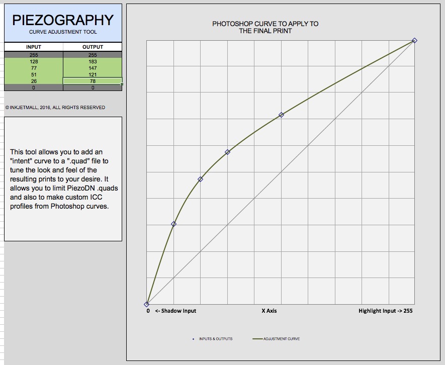
When I have something I think will work I transfer the 4 input/output pairs to the Piezography Curve Adjustment Tool and follow the procedure for making adjusting the .quad.
[attachment file=26250]
I would name the new .quad MH-Master (for Metal Halide) or something like that. Then test it as you would with the regular Master, and make a linearization from the results of that.
The reason Art started this thread was his concern about what he was seeing in the CurveView of the .quad curves he was coming up with which show a lot of ink in the dense region of the negative. This is directly related to the amount of density needed to block UV light to create a linear result. There is something about the interaction of the printing process, the ink on film, and the exposure light that is having a very unusual result. I don’t know what it is. I can say that I have in the past worked with a similar metal halide light (Olec AL15 w/ L-1250E lamp - similar spectral output to those used by Art, Gilles, Rafael, etc.) side-by-side with a BL fluorescent (350nm peak output). With traditional large format film negatives there was no significant difference in the way Pt/Pd prints responded. I never used the Olec with digital negatives though.
I’m pretty sure that eventually Walker will come up with a better way of making a Master tuned specifically for these metal halide units, but until then I hope this will help make the linearization process a little easier for those of you using them.