Hi, ok cut the paper along the line to ensure was straight, I also made sure i applied light but firm pressure when feeding the target. Alas still the same false readings
I have cleaned the dtp70 as per the manual.
Might try a create a new curve from the master target and see how that looks!
There i was staring at the screen trying to work out if what could possible be wrong, when i noticed that in the correction column there was already some additions?
I did not put them there, and had selected all and cleared contents for curves!
I am beginning to think that they may have been in there from a previous paper and remained there as i had not closed excel?
Going to add to my Linearize workflow to ensure excel has been closed and reopened afresh before doing a new linearization as once these were removed from the correction column all looked much better with just 2 false readings.
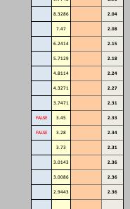
It is not always the steps indicated as false that are the problem. Sometimes it is the step(s) just below (or posiibly just above) that is throwing things off, and that looks to be the case here. The 4th step up from the bottom is 3.73, and it is this step that is causing the 2 above it to register as false. If you change it to something like 3.13 the falses will no longer be false.
The situation is similar in your previous example with the long string of 16 falses. It is the last 4 readings that are throwing it off.
Most of my own experience is making curves is for alternative wet darkroom processes which in many cases produce more (and more pronounced) false readings due to the measurement device errors being compounded by ink deposition irregularities on the negative compounded by coating irregularities on the print, etc. In most cases, unless it is something obvious at one extreme or the other, I have found it best to let the software sort it out. Your issue here is at the lower extreme so it is probably beneficial to fix it manually, though it is important to choose carefully the step(s) that should be changed. You may even be able to tell visually by looking closely at the target print which readings are wrong.
Keith
PS - Sorry if this is obvious; it wasn’t to me at first.
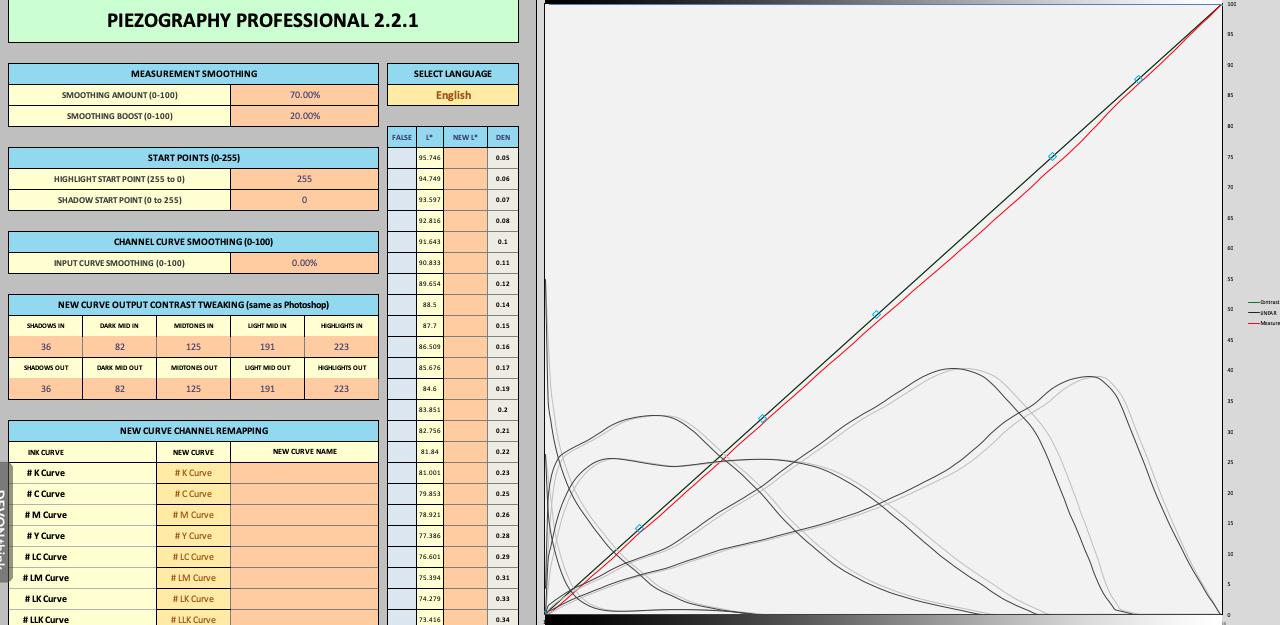
Ok created a new curve with correction suggestion from jkschreiber and printed new dtp700 target, a quick dry with hair dryer and this was the results:
Ok holidays over and back to the learning curve, excuse the pun
I tried linearizing canson photographique Rag 310 on my 4800 which same printer i have used for last 2 papers linearized, method:
Target = Piezography-700step-DTP70
Curve used to print target = P2-CAR-UHD-MASTER
Measured with colorport and DTP70
Print target with P2-CAR-UHD-MASTER, dry 24hrs, measure and create new curve and print target with new curve, dry for 24hrs. Measure and create new final curve.
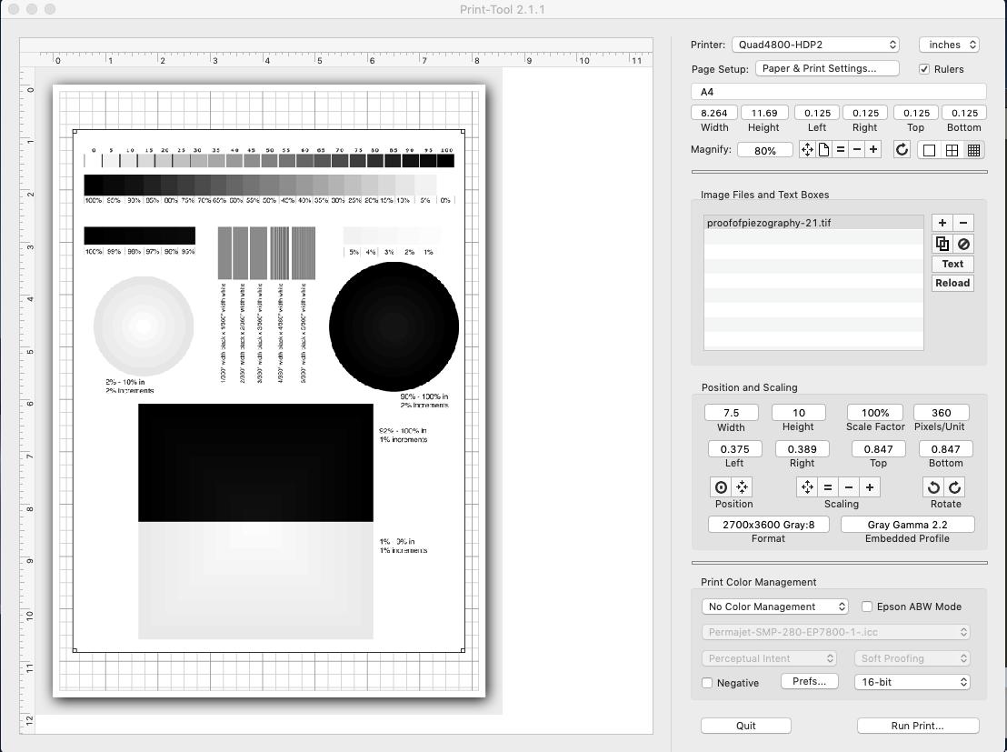
The one problem that comes up with this printer is very dark almost black shadows in prints, comparing proof of piezography prints from this 4800 and my 1500w there is a clear difference.
Black circle 90% - 100% in 2% increments
1500w - Can see the transitions
4800 - Can only see the last 3 transitions in the middle, the rest just black
Black rectangle 92% - 100% in 1% increments
1500w - Have to look harder, but can see all transitions
4800 - Have to look very hard to see first 3 transitions from bottom, the rest just black.
Printing the Control 10 Channel Ink Separation image in calibration mode i can see the 90% 95% 100%
patches on K, MK have ink bleeding on leading edge of patch, the last past being slightly worse.
Questions is how to resolve this?
Can this be fixed on a printer level? Printer has new dampers and nozzle checks look good.
or
Change shadow start or limit inking? if this what settings to try.
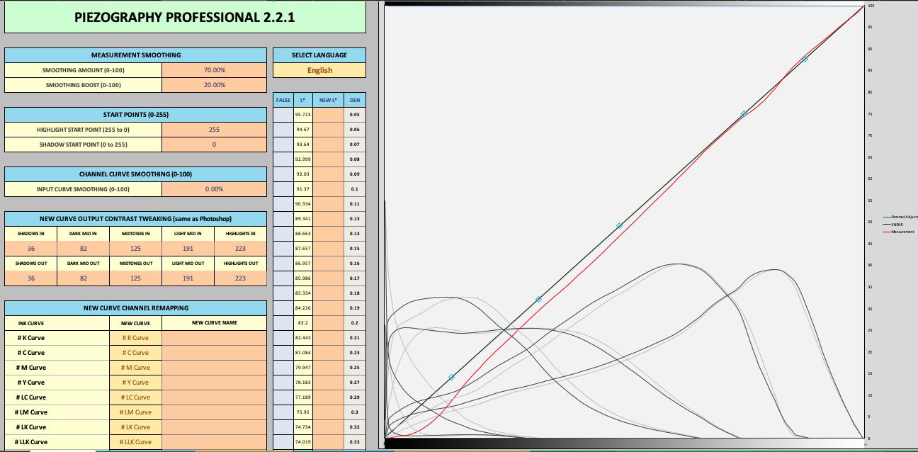
Here is the results of last printed target, no start curve.
Please show (high resolution enough) screenshots of your print workflow.
The screenshot above shows a relatively linear valid curve so there is no reason why it would print dark unless there is some profile mess-up or other thing.
To be honest not sure these last two images actually show much when viewed online, but trust me there is big difference how you can see the transitions.
Still looking for a solution to the dark shadows in prints.
I am currently creating a new curve for epson enhanced Matt as I have plenty of this paper and is cheaper than fine art papers to use while solving this issue.
I have printed 1s target and new curve, second printed target from new curve is drying.
Walker I have pm you a link to video of my workflow
He is my workflow
Paper Target Names
Printer Ink Type - Curve used Paper Type Curve Stage date
4800 P2 Carbon - P2-CAR-UHD-MASTER Curve -EpEnhMatt V1 /01/2020
Ensure room at correct temperature and within humidity levels
Ensure printer clean and printing well
Print purge page to ensure no stale ink in lines
Prepare paper
Blow paper clean with can of air
Feed paper into printer (not in via tray)
Load up print tool
Select image Piezography-700step-DTP70.tiff
Align image to top of paper
Add text to identify printed patch
Select correct Printer
Set correct paper size
Select - No color Management & 16bit
Select Run Print
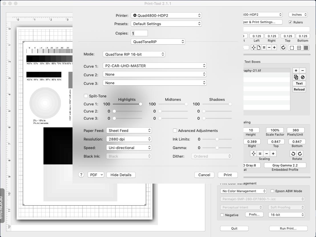
Ensure correct printer chosen
From drop menu with ‘layout’ select quadtone rip
Mode = QuadTone Rip 16 bit
Curve 1 = Curve to use for target, usually start with master
Paper Feed = Sheet Feed
Resolution = 2880 dpi
speed = uni-directional
leave rest as default
Print
Check printed target
Dry with hair drier 30 secs
If GO overcoat needed leave for 30 min, print GO
Dry 24hrs in airing cupboard
Measure with DTP70 using colorport
Save as text file > conversion none - line ending Macintosh - lab - d50 observer 2
Load Piezography Professional tool in excel
Clear both Measurements and Starting Curve tabs:
Select all > Right click 1st cell > clear contents
Open newly measured target txt file
Select all > copy
Go Back to excel, click in 1st cell in Measurement tab, paste
Open the master curve used to print target
Select all > copy
Go Back to excel, click in 1st cell in Starting Curve tab, paste
Adjust as required, normally just smoothing
Click on create new curve tab, copy
Create new txt file
paste new quad data
Save file as quad file in correct Printer curve folder ie
Application > Piezography > Curves-HD > 4800-7800-9800-P2
Reinstall this printer
Repeat the above target printing procedure except this time using the newly created curve to print target.
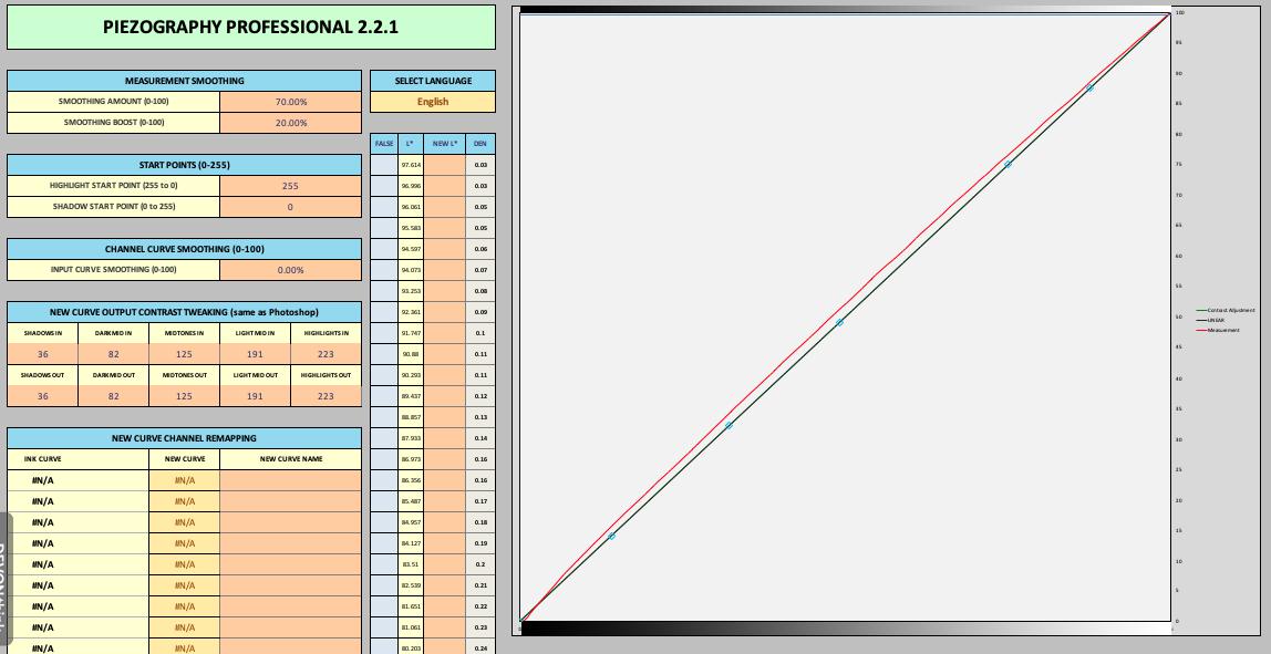
The video you showed is fine but does not show the validation measurement. It should be a straight line. If it is and your shadows are still dark than either you are soft-proofing wrong or your monitor/workspace is problematic.
Thanks for reply,
Will print a validation target tomorrow.
Not sure my soft proofing is an issue as I am specifically speaking about the proof of piezography image and the shadow transition in that, i am making no edits just printing your image.
The one problem that comes up with this printer is very dark almost black shadows in prints, comparing proof of piezography prints from this 4800 and my 1500w there is a clear difference.
Black circle 90% - 100% in 2% increments
1500w - Can see the transitions
4800 - Can only see the last 3 transitions in the middle, the rest just black
Black rectangle 92% - 100% in 1% increments
1500w - Have to look harder, but can see all transitions
4800 - Have to look very hard to see first 3 transitions from bottom, the rest just black.
When i view this same image in photoshop (100%) for the Black circle 90% - 100% in 2% increments from the center i can see 5 lines showing transition.
When i view this same image in photoshop (100%) for the Black rectangle 92% - 100% in 1% increments from the bottom i can see 7 lines showing transition.
I am using a calibrated Coloredge CG241W
The Epson Enhanced Matt i created a curve for over last few days is looking better, when doing a proof of piezography image print, although not very easy, in the right light and viewing angle i can see a lot more transition in circle and rectangle, will let it dry over night for good check tomorrow.
I have looked at the proof of piezography image print this morning after overnight dry.
Black circle 90% - 100% in 2% increments
Black rectangle 92% - 100% in 1% increments
In both of these i can see the incremental changes, it is not easy requiring bright light and viewing at a certain angle, but is much better than the other papers (canson platine, baryta Photographique, rag photographique, Ilford GFS i have profiled on this 4800 printer which show little or no incremental changes.
This differs from profiles i have created on my 1500w for canson for Edition Etching Rag & Velin Museum Rag where i can see the incremental changes on the black circle black rectangle without difficulty.
I am pretty sure my workflow and workspace settings are all good. When loading the rgb shadow checker image in photoshop i can see all number 1 > 63 with the 1 being just visible.
I am going to try profiling canson platine again and see if i can improve things, but i feel this maybe a printer issue.
Have printer the final validation target for the new created curve for epson enhanced matt, will let it dry overnight and see how it looks.
Ahh, this is why. Linear contrast is paper dependent. It is faithful to the contrast ration of the paper. A matte paper (1500 printer) is going to show much more shadow sep. than a gloss paper (platine) because the gloss is at a higher contrast ration. They are supposed to look the same (between matte an gloss) and even require different contrast curve adjustments (under preserve rgb soft proofing profiles) for a print on matte vs a print on gloss.
Ok that is a lot to take in, but the gist of it is that matt will show greater shadow separation than gloss.
Are saying different printers 15002 vs 4800 will also show different shadow separation?
If not i still may have an issue as there is clearly a difference in shadow separation on the epson enhanced matt paper i have profiled on the two printers, the K6 special edition on the 1500w shows greater shadow separation.
I will play with the contrast curves till find what i am happy with and create curve for that paper with contrast curve included.
If you soft proof with the correct profile (Piezography Matte Print) with Preserve RGB Numbers turned on this should give you a decent match to a linear print on matte paper . . . same (respectively) for gloss. it will flatten out your image and then you add 1 contrast curve to get back your contrast. This open/close process in photoshop is more work but gives you full control of shadows with screen-to-print match that is more stable than either tweaking w/ a contrast curve in PPEv2 or printing with an actual ICC from print tool.