Learning to correct a curve

  1. Make sure you are printing in gray gamma 2.2.
  2. Please show (high resolution enough) screenshots of your print workflow.

The screenshot above shows a relatively linear valid curve so there is no reason why it would print dark unless there is some profile mess-up or other thing.

best regards,
Walker

Hi and thanks for reply.

I am printing in gamma 2.2, here are screen shots of workflow.

Here is link to hi res photo I took of proof of piezography.

https://drive.google.com/file/d/1XCR-yBjoLfZqHRJku_yhbAw4bvvFhHDx/view?usp=drivesdk

And here Hi res photo of proof of piezography from 1500w

https://drive.google.com/file/d/1D8n0T9zDD1CHamLjZoTBKuxVkwWnZUm_/view?usp=drivesdk

To be honest not sure these last two images actually show much when viewed online, but trust me there is big difference how you can see the transitions.

thanks

Why are you printing with the master curve instead of the calibrated curve?

I just pulled that curve up to show workflow settings, I only used master curve for initial target, after that the new custom curve was used.

Thanks

Still looking for a solution to the dark shadows in prints.

I am currently creating a new curve for epson enhanced Matt as I have plenty of this paper and is cheaper than fine art papers to use while solving this issue.

I have printed 1s target and new curve, second printed target from new curve is drying.

Walker I have pm you a link to video of my workflow

He is my workflow

Paper Target Names

Printer Ink Type - Curve used Paper Type Curve Stage date
4800 P2 Carbon - P2-CAR-UHD-MASTER Curve -EpEnhMatt V1 /01/2020

Ensure room at correct temperature and within humidity levels
Ensure printer clean and printing well
Print purge page to ensure no stale ink in lines

Prepare paper
Blow paper clean with can of air
Feed paper into printer (not in via tray)
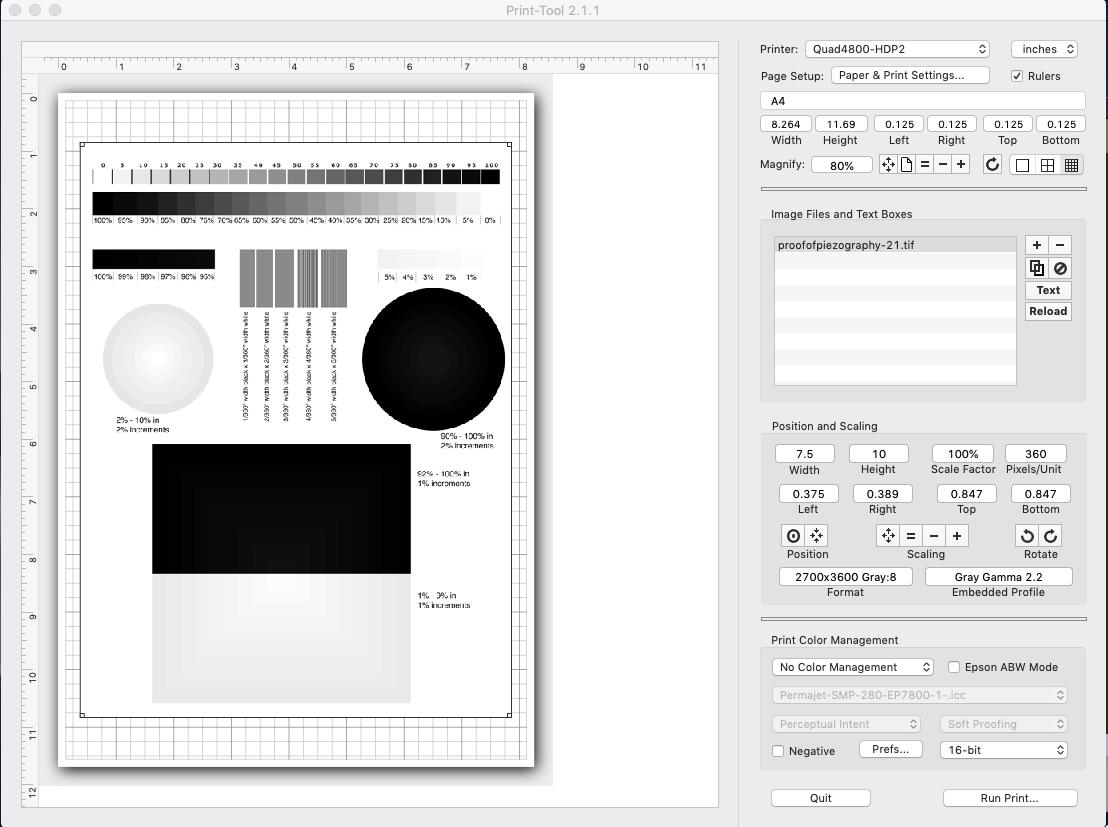
Load up print tool
Select image Piezography-700step-DTP70.tiff
Align image to top of paper
Add text to identify printed patch
Select correct Printer
Set correct paper size
Select - No color Management & 16bit
Select Run Print

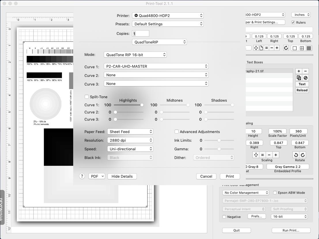
Ensure correct printer chosen
From drop menu with ‘layout’ select quadtone rip
Mode = QuadTone Rip 16 bit
Curve 1 = Curve to use for target, usually start with master
Paper Feed = Sheet Feed
Resolution = 2880 dpi
speed = uni-directional

leave rest as default

Print

Check printed target
Dry with hair drier 30 secs
If GO overcoat needed leave for 30 min, print GO
Dry 24hrs in airing cupboard

Measure with DTP70 using colorport
Save as text file > conversion none - line ending Macintosh - lab - d50 observer 2
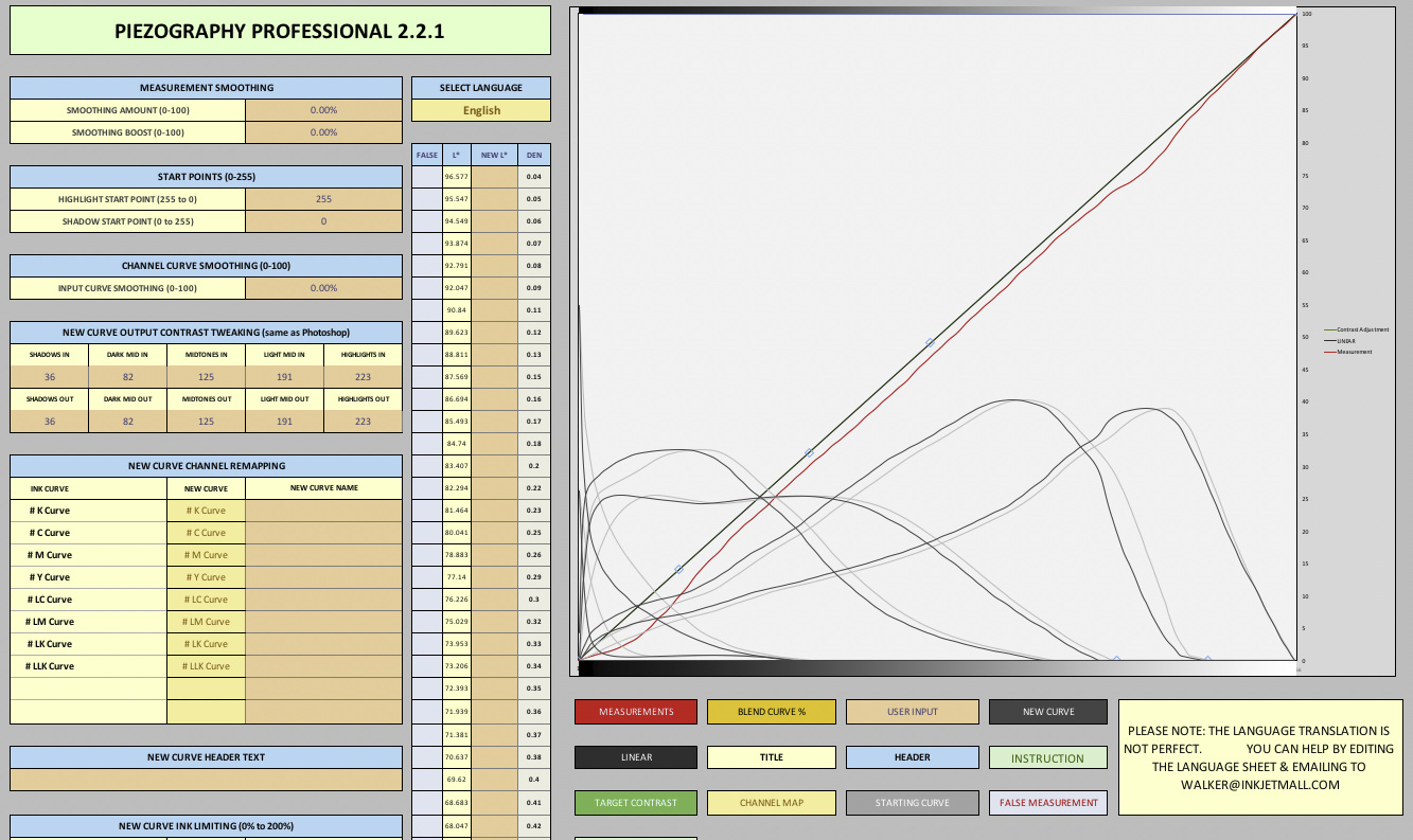
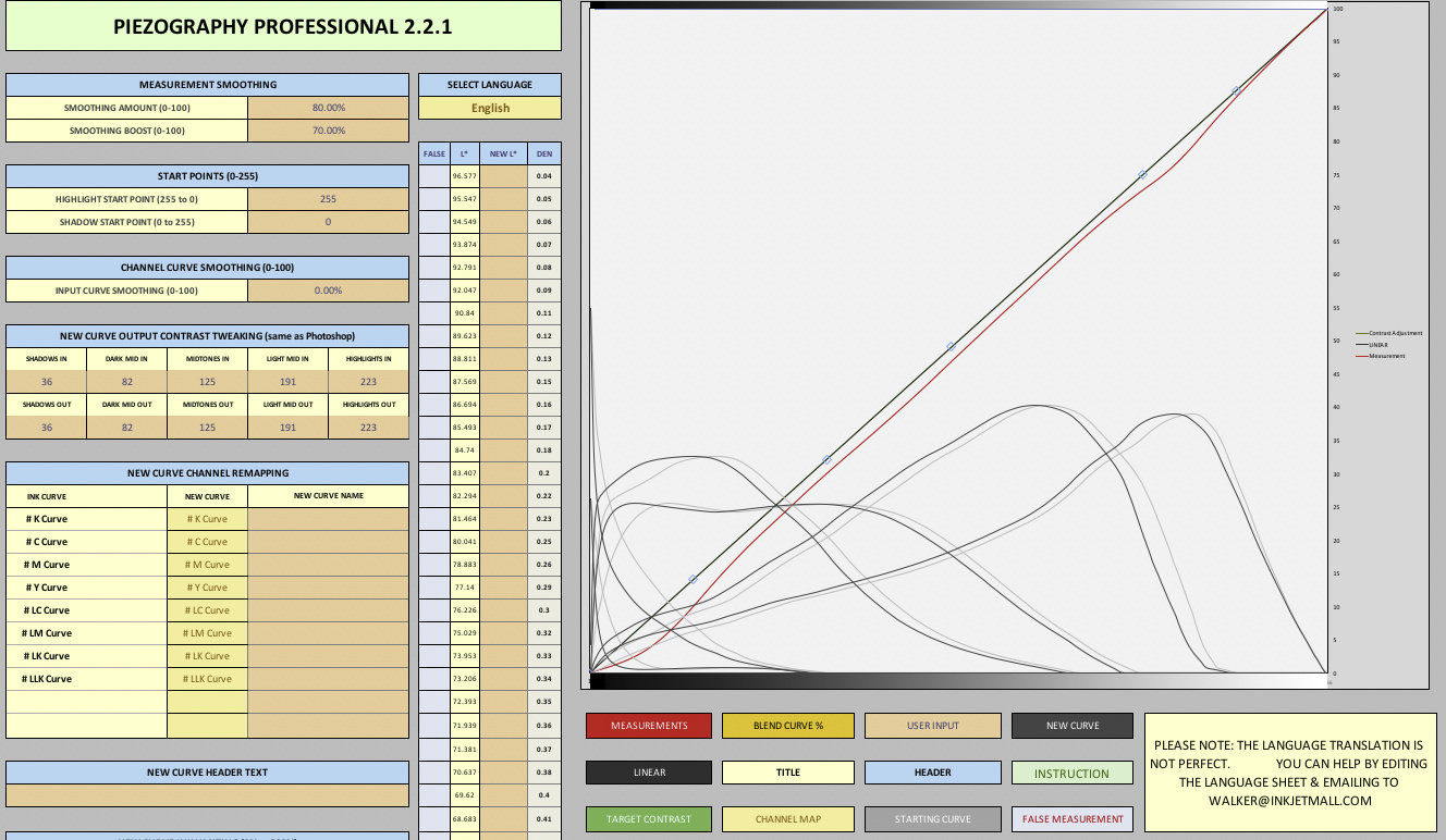
Load Piezography Professional tool in excel
Clear both Measurements and Starting Curve tabs:
Select all > Right click 1st cell > clear contents

Open newly measured target txt file
Select all > copy

Go Back to excel, click in 1st cell in Measurement tab, paste

Open the master curve used to print target
Select all > copy

Go Back to excel, click in 1st cell in Starting Curve tab, paste

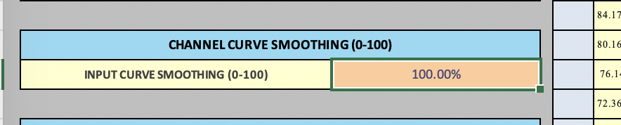
Adjust as required, normally just smoothing

Click on create new curve tab, copy

Create new txt file
paste new quad data
Save file as quad file in correct Printer curve folder ie
Application > Piezography > Curves-HD > 4800-7800-9800-P2
Reinstall this printer

Repeat the above target printing procedure except this time using the newly created curve to print target.

Text/Quad files created using Sublime text

The video you showed is fine but does not show the validation measurement. It should be a straight line. If it is and your shadows are still dark than either you are soft-proofing wrong or your monitor/workspace is problematic.

-Walker

Thanks for reply,
Will print a validation target tomorrow.

Not sure my soft proofing is an issue as I am specifically speaking about the proof of piezography image and the shadow transition in that, i am making no edits just printing your image.

The one problem that comes up with this printer is very dark almost black shadows in prints, comparing proof of piezography prints from this 4800 and my 1500w there is a clear difference.

Black circle 90% - 100% in 2% increments
1500w - Can see the transitions
4800 - Can only see the last 3 transitions in the middle, the rest just black

Black rectangle 92% - 100% in 1% increments
1500w - Have to look harder, but can see all transitions
4800 - Have to look very hard to see first 3 transitions from bottom, the rest just black.

When i view this same image in photoshop (100%) for the Black circle 90% - 100% in 2% increments from the center i can see 5 lines showing transition.

When i view this same image in photoshop (100%) for the Black rectangle 92% - 100% in 1% increments from the bottom i can see 7 lines showing transition.

I am using a calibrated Coloredge CG241W

The Epson Enhanced Matt i created a curve for over last few days is looking better, when doing a proof of piezography image print, although not very easy, in the right light and viewing angle i can see a lot more transition in circle and rectangle, will let it dry over night for good check tomorrow.

thanks

I have looked at the proof of piezography image print this morning after overnight dry.

Black circle 90% - 100% in 2% increments
Black rectangle 92% - 100% in 1% increments

In both of these i can see the incremental changes, it is not easy requiring bright light and viewing at a certain angle, but is much better than the other papers (canson platine, baryta Photographique, rag photographique, Ilford GFS i have profiled on this 4800 printer which show little or no incremental changes.

This differs from profiles i have created on my 1500w for canson for Edition Etching Rag & Velin Museum Rag where i can see the incremental changes on the black circle black rectangle without difficulty.

I am pretty sure my workflow and workspace settings are all good. When loading the rgb shadow checker image in photoshop i can see all number 1 > 63 with the 1 being just visible.

I am going to try profiling canson platine again and see if i can improve things, but i feel this maybe a printer issue.

Have printer the final validation target for the new created curve for epson enhanced matt, will let it dry overnight and see how it looks.

thanks

Ahh, this is why. Linear contrast is paper dependent. It is faithful to the contrast ration of the paper. A matte paper (1500 printer) is going to show much more shadow sep. than a gloss paper (platine) because the gloss is at a higher contrast ration. They are supposed to look the same (between matte an gloss) and even require different contrast curve adjustments (under preserve rgb soft proofing profiles) for a print on matte vs a print on gloss.

tldr: You are fine.

-Walker

Ok that is a lot to take in, but the gist of it is that matt will show greater shadow separation than gloss.

Are saying different printers 15002 vs 4800 will also show different shadow separation?

If not i still may have an issue as there is clearly a difference in shadow separation on the epson enhanced matt paper i have profiled on the two printers, the K6 special edition on the 1500w shows greater shadow separation.

I will play with the contrast curves till find what i am happy with and create curve for that paper with contrast curve included.

thanks

If you soft proof with the correct profile (Piezography Matte Print) with Preserve RGB Numbers turned on this should give you a decent match to a linear print on matte paper . . . same (respectively) for gloss. it will flatten out your image and then you add 1 contrast curve to get back your contrast. This open/close process in photoshop is more work but gives you full control of shadows with screen-to-print match that is more stable than either tweaking w/ a contrast curve in PPEv2 or printing with an actual ICC from print tool.

best regards,
Walker

Great lot to still learn, but getting there, don’t get me wrong my prints are not looking terrible, in fact in the last few years i have been at the local camera club i have won the print league, print of the year twice and my prints are always very well received as there are at monochrome club i sometimes go to.

Just want to now up my game and get much better.

thanks

The new canson platine target from the p2 carbon HDPK master has dried over night and this is the result.


Is this acceptably linear? I see big bump in red line at bottom and top.
No errors and I decided on smoothing of 80 - 70

thanks

1 Like

all looks good :slight_smile:

You are on the rd of printing!

best,
Walker

Ok have redone from scratch both Ifford Gold Fibre Silk (original as have box a2) and cason platine.

First target from P2-CAR-HDPK-MASTER
Second Target (validation) from new curves

GFS > new curve smoothing 80 / 40
The validation target has dmax 2.22 and looks pretty good, with possible the darker inks pushed to the left a bit.
no smoothing added to below

When I printed a test print i noticed the the radial gradient had banding in the lighter section, so i printed a larger more detailed radial gradient greyscale linearization image with same curve and created another curve with increased smoothing 80 60 and printed the detailed radial gradient, thing is the banding looks slightly worse with increased smoothing?

The tonal value that is show banding in the radial gradient greyscale linearization is 2

Both the b&w test print and radial gradient greyscale linearization can be found here

this the radial gradient greyscale linearization image, again it is the tonal range 2 that is showing the banding

I was of the understanding that increasing the smoothing would remove the banding? I am not seeing this on any other paper?

Platine > new curve smoothing 90 / 70
The validation target has dmax 2.36 and looks pretty good, except possible the deep shadows?
The darker inks seem to be pushed to left, i have not yet printed a test image, this just me trying to learn to read the curves.
No smoothing applied to below

thanks

banding is generally caused by squiggles introduced into the actual ink curves due to measurement falses not being properly smoothed out previously. You don’t fix this by smoothing the current measurement, what you do is you import the curve that is banding a bit, delete any measurements that are in the tool, and then set the “Input Curve Smoothing” to 100% and print with the resulting “New Curve” which will have a smoothed histogram.

See, a tool for everything!

best regards,
Walker

Tried that and works a treat, another thing learnt :slight_smile:

Even did another smooth version with very slight contrast curve and my test print is looking great and about 98% accurate to my freshly calibrated monitor with softproof with preserve rgb numbers :slight_smile:
Happy days

On to more paper

Thanks