Hi, I am really trying to improve my understanding or curve correction, i have read the manual and watched the video. From what i understand the two main setting to help correct a curve are:
Smoothing - amount/boost
input curve smoothing
I have done a few paper recently and although i not sure they are the best i can get, the prints look good.
I am trying a matt paper (pinnacle fine art smooth) that worked well on 1500w with SE inks, this time on my 4800 with P2 carbon inks.
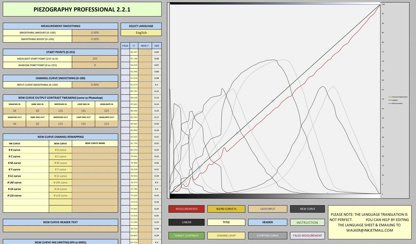
Target = Piezography-700step-DTP70
Curve used to print target = P2-CAR-UHD-MASTER
Measured with colorport and DTP70
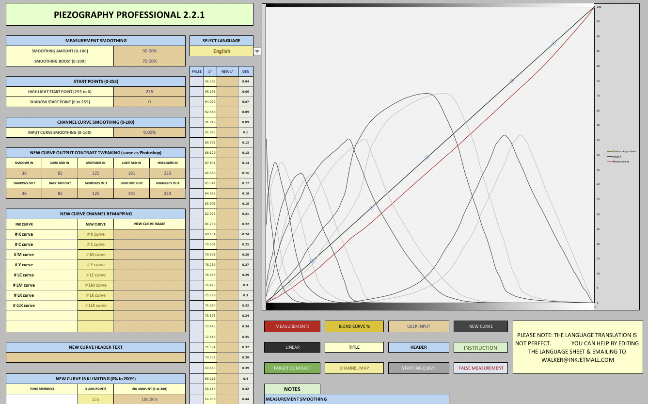
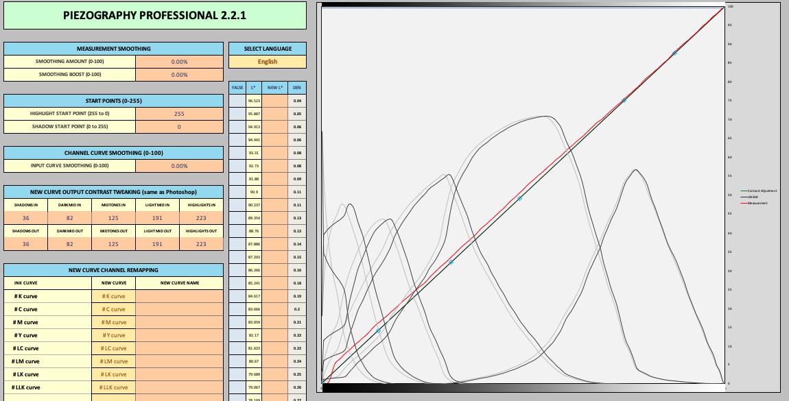
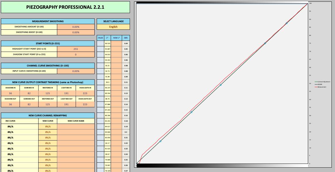
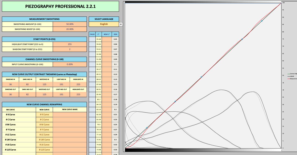
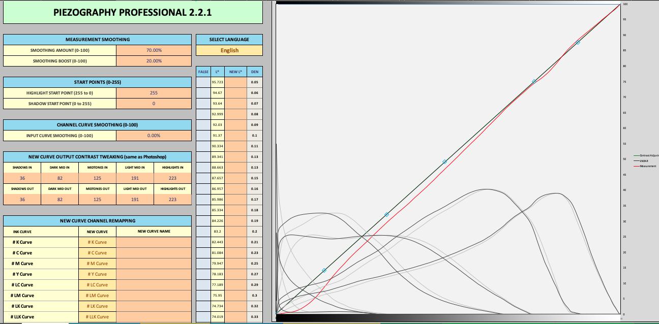
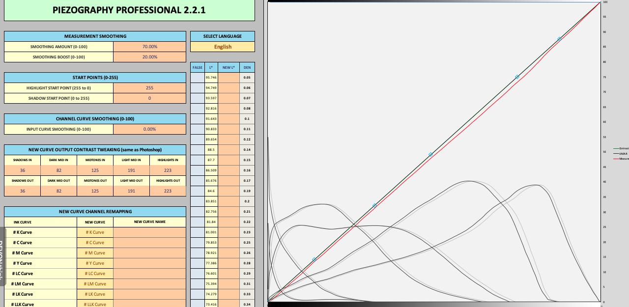
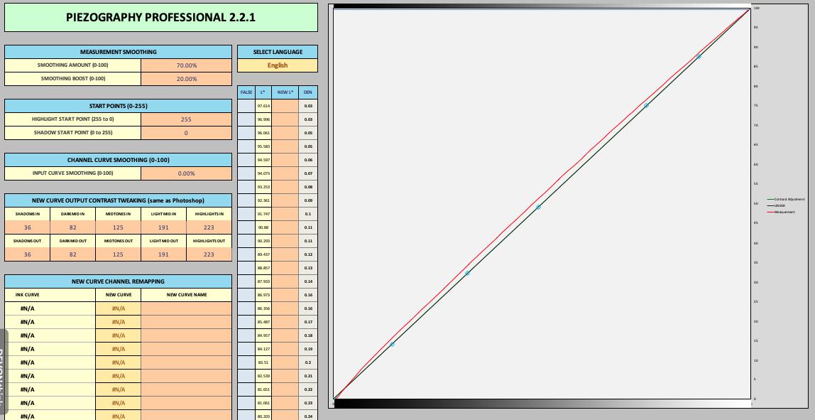
The first image is with no adjustments, the second is with Smoothing - amount/boost, 90 / 70%
input curve smoothing did not appear to do anything.
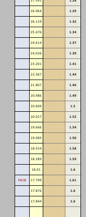
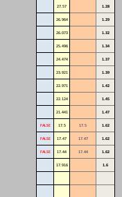
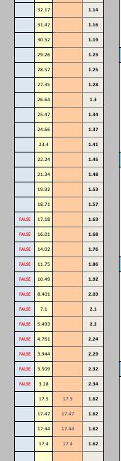
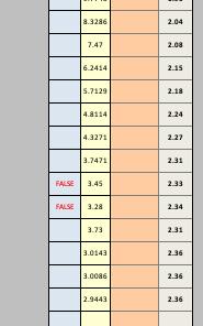
There are a few false reading toward the bottom, with one being 1.61
The lowest reading being 1.48 but not a false
(non UHD ink)
Anything else i should adjust, or change existing adjustments?
One other thing, after creating a new curve, do i need to use new curve to print a new target and then and then readjust if required and create another new curve?
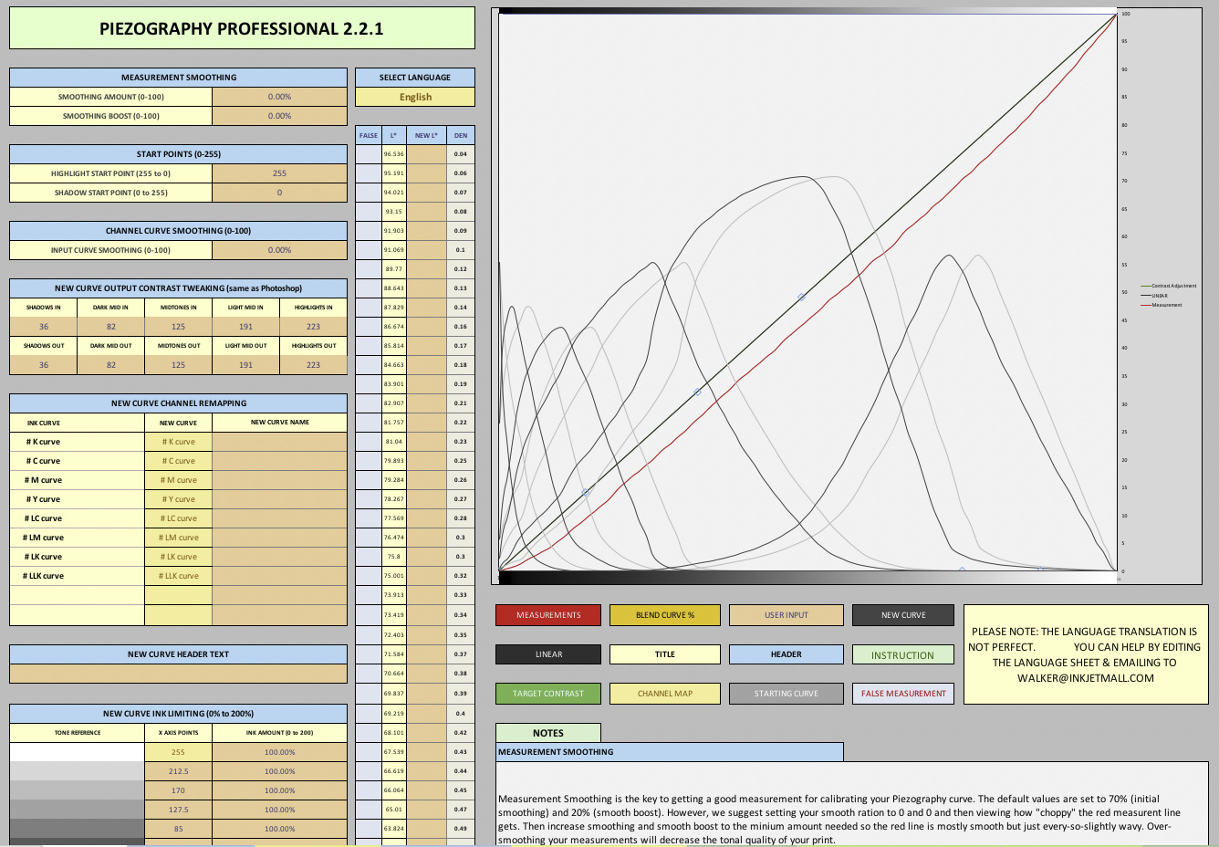
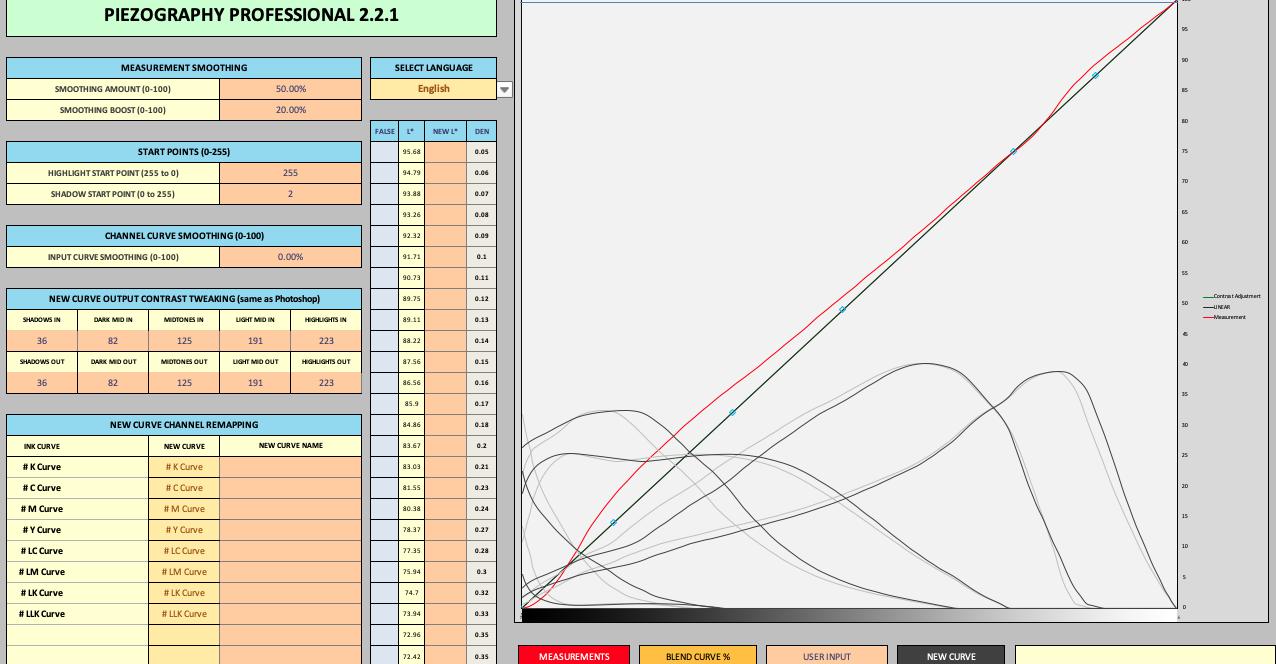
So it looks to me like your measurement device is not being placed directly over the patch values and this is causing the reversals there. It should be smoother than it is even at “zero” smooth setting.
In general though the initial curve was pretty linear and your printer looks like it just puts out a bit more ink than normal causing a linear but darkish print. You are doing the right think by smoothing and linearizing and printing with this new curve.
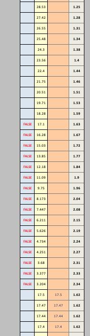
you have over-inking on the last patch. Manually correct for this (type in 17.4) and then set your “Shadow Start Point” to 2 and the curve should be fine.
I did create a new curve without changing the start, as to dried, it was dried 24hrs in my airing cupboard so most certainly was dried enough.
I printed a proof of piezography and and what i am seeing is that in the black circle 90% 100% in 2% inc and black rectangle 1% 9% 1% inc the ability see the changes in these is very difficult compared to same paper i profiles on my 1500w with SE inks, other papers such as EE show greater shadow detail.
I have plenty of canson platine A4 so am going to try and profile this paper with both the default curve and master curve and see how that looks.
Looks to me like you need to cut the target more exactly and also gently push the sheet into the rollers from directly middle/back of the paper sheet on the first feed “swoop”. These machines can be finicky.
Thanks for reply, the target sheets are supplied A4 so should be straight, I also do apply some pressure when feeding the paper as recommended in the manual.
I will try cutting along the line printed by the target and rescan.
Hi, ok cut the paper along the line to ensure was straight, I also made sure i applied light but firm pressure when feeding the target. Alas still the same false readings
I have cleaned the dtp70 as per the manual.
Might try a create a new curve from the master target and see how that looks!
There i was staring at the screen trying to work out if what could possible be wrong, when i noticed that in the correction column there was already some additions?
I did not put them there, and had selected all and cleared contents for curves!
I am beginning to think that they may have been in there from a previous paper and remained there as i had not closed excel?
Going to add to my Linearize workflow to ensure excel has been closed and reopened afresh before doing a new linearization as once these were removed from the correction column all looked much better with just 2 false readings.
It is not always the steps indicated as false that are the problem. Sometimes it is the step(s) just below (or posiibly just above) that is throwing things off, and that looks to be the case here. The 4th step up from the bottom is 3.73, and it is this step that is causing the 2 above it to register as false. If you change it to something like 3.13 the falses will no longer be false.
The situation is similar in your previous example with the long string of 16 falses. It is the last 4 readings that are throwing it off.
Most of my own experience is making curves is for alternative wet darkroom processes which in many cases produce more (and more pronounced) false readings due to the measurement device errors being compounded by ink deposition irregularities on the negative compounded by coating irregularities on the print, etc. In most cases, unless it is something obvious at one extreme or the other, I have found it best to let the software sort it out. Your issue here is at the lower extreme so it is probably beneficial to fix it manually, though it is important to choose carefully the step(s) that should be changed. You may even be able to tell visually by looking closely at the target print which readings are wrong.
Keith
PS - Sorry if this is obvious; it wasn’t to me at first.
Ok created a new curve with correction suggestion from jkschreiber and printed new dtp700 target, a quick dry with hair dryer and this was the results:
Ok holidays over and back to the learning curve, excuse the pun
I tried linearizing canson photographique Rag 310 on my 4800 which same printer i have used for last 2 papers linearized, method:
Target = Piezography-700step-DTP70
Curve used to print target = P2-CAR-UHD-MASTER
Measured with colorport and DTP70
Print target with P2-CAR-UHD-MASTER, dry 24hrs, measure and create new curve and print target with new curve, dry for 24hrs. Measure and create new final curve.
The one problem that comes up with this printer is very dark almost black shadows in prints, comparing proof of piezography prints from this 4800 and my 1500w there is a clear difference.
Black circle 90% - 100% in 2% increments
1500w - Can see the transitions
4800 - Can only see the last 3 transitions in the middle, the rest just black
Black rectangle 92% - 100% in 1% increments
1500w - Have to look harder, but can see all transitions
4800 - Have to look very hard to see first 3 transitions from bottom, the rest just black.
Printing the Control 10 Channel Ink Separation image in calibration mode i can see the 90% 95% 100%
patches on K, MK have ink bleeding on leading edge of patch, the last past being slightly worse.
Questions is how to resolve this?
Can this be fixed on a printer level? Printer has new dampers and nozzle checks look good.
or
Change shadow start or limit inking? if this what settings to try.
Here is the results of last printed target, no start curve.