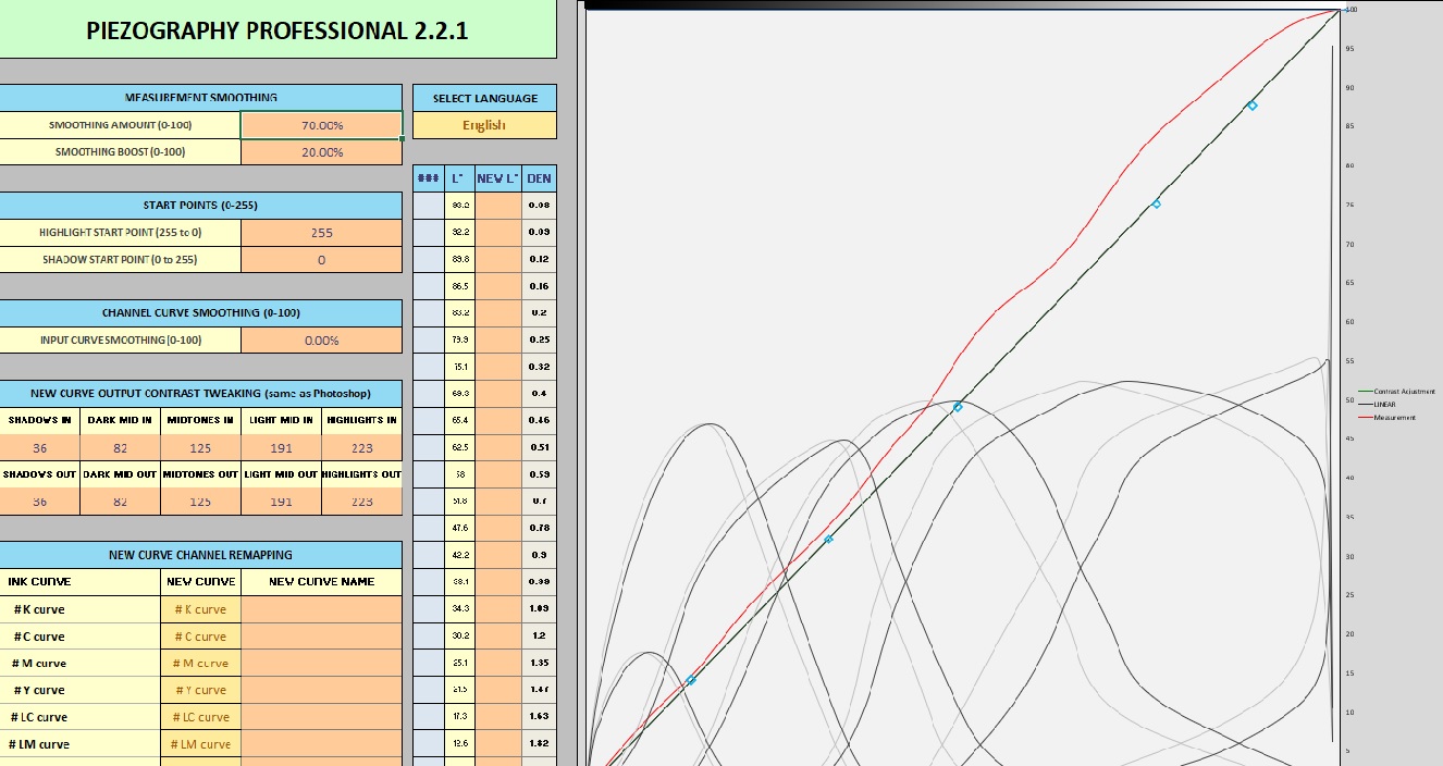
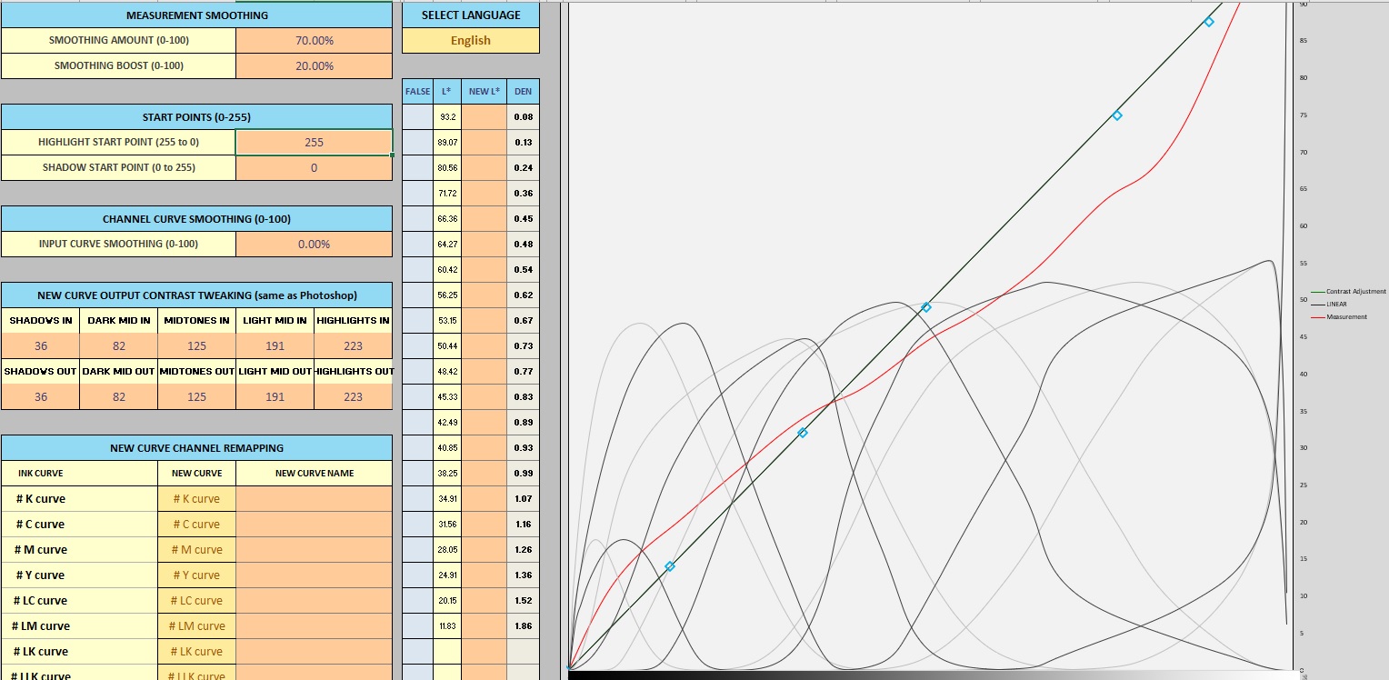
I have followed Walker’s video the best I can and this is the result I get in Excel.
Instructions for what? What is it that you are trying to do? And what steps have you taken?
This looks like the same issue that I had the last time I made readings for curves. Turns out that I was not scanning the patches correctly. I was used to scanning a129 patch color monkey target, which read left to right for each row. I printed a 129 patch XRITE i1Pro target and started to read the patches left to right as I had done previously. after doing this a couple of times, I slowed down and realized that the i1Pro targets I had printed needed to be read each collum from top to bottom (horizontal printed), then each collum from left to right.
so all set on your end now?
As @keithr said, you need to ensure the measurement data is measured correctly. The luminance values Lab_L should be decreasing from highest to lowest in the measurement .txt file when you open it in a text editor.
If you are measuring with i1Profiler and an i1Pro v2 (RevD) device I suggest using the 21x16 target. This will give you the most accurate measurement for a starting calibration.
regards,
-Walker
Yep! After I had realized the issue, I had no problem.
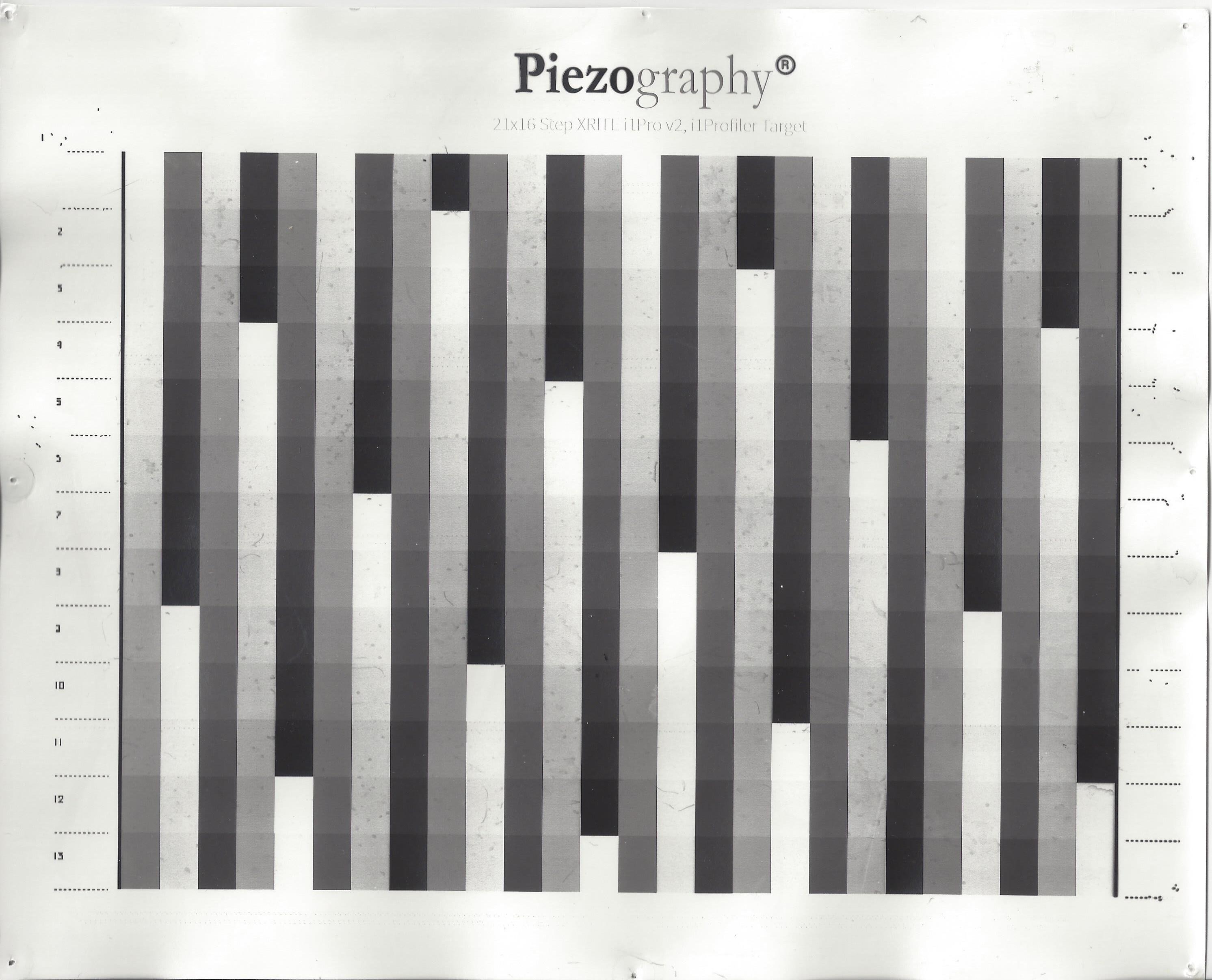
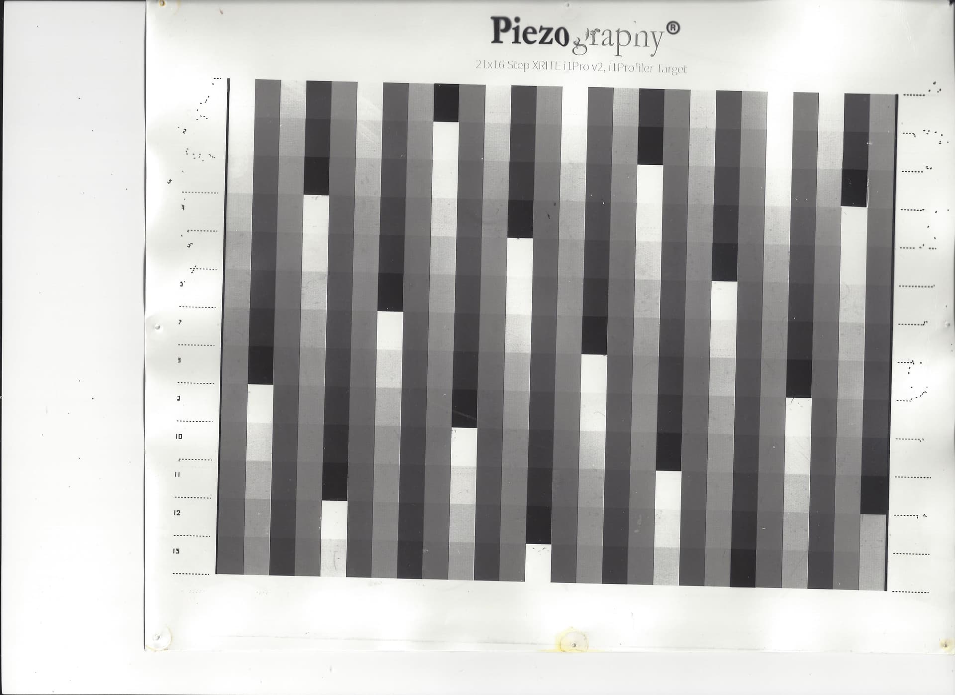
I am sorry I did not include enough information. I am using a PC running Windows 10. This is the 21 x 16 target and I have the i1Profiler Pro. I am trying to make a curve for Carbon printing. I printed the negative using QTR, Printing model: Quad3880-PiezoDM-Pro, Curve: Pro-PiezozDN-Master. I read the target from left to right single pass. I have included a copy of my Carbon print of the 21 x 16 target.
Thank you for your help.
Jim
Jim,
This is greatly over-exposed. It’s asking too much of the profiler.
You need first ascertain your optimum exposure by step wedge exposure test.
Then do this part again, using that exposure time, so that it is not overexposed and try measuring again.
Kindest regards,
Jon`
Here is my suggestion. Do not start with special paper. Instead, stay with pieozography print and test your system on a standard paper where the profile is very precise and is provided to you. This test (or retest) allows you to find where your calibration process breaks down. With a curve that you know will work, run the test on that and remeasure the new curve and see if you get approximately the same curve that they gave you. It will not be the same because of some sampling error but it should be so close that you cannot tell when you look at the new 21 x 16 target. If there is a problem with your 21 x 16 target, it will appear somewhere in the process that you use. You must follow the video exactly! The system is quite strict. Walker’s video is quite good. Any misinterpretation by you may cause the result to fail.
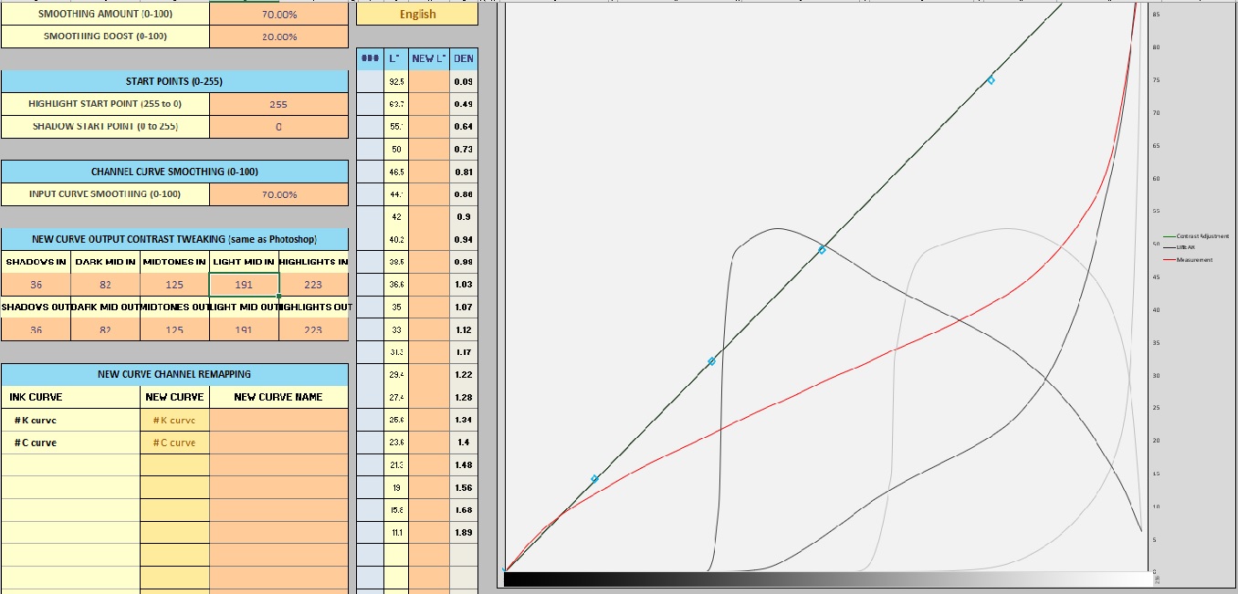
This is my latest try at making a curve for a digital negative to make Carbon prints. Does the target exposure look good, over exposed, under exposed or good? Any ideas how I can get a better looking curve?
Could I be fighting an uphill battle because Carbon prints whites on the target are not perfectly clean and other Carbon gremlins.
Thanks to all for reading and responding.
Jim
et
and cut the exposure
Hi Jim,
This is soooooo much better than where you started at the beginning of the thread. You’re a little dark in the highlights and a little light in the shadow. This should get corrected.
So, that was step #1. You zeroed in on a better exposure. Measured the target produced from printing it with the base starting curve.
You should copy and paste the data from New Curve into the old curve and Save As with a new name…
Step #2 will be to print the same target with the new curve you saved, measure it and see how linear you are. We call that the Validation. We would normally save that new curve as our printing curve.
Let us know how that turns out!
Wishing you a fantastic 2024,
Jon
Jon,
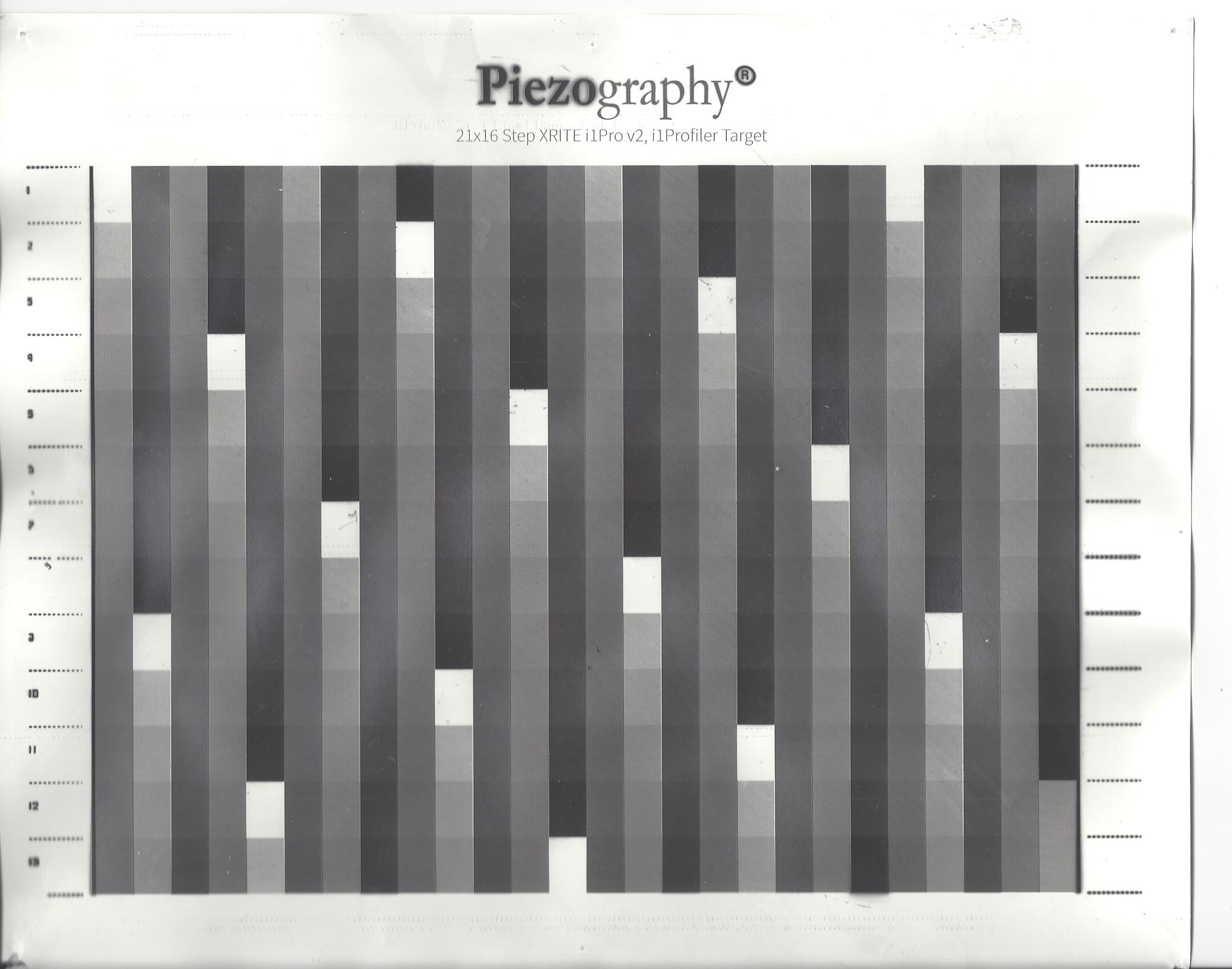
This target was printed with a new curve (Kremer-2gr-300units) not the Pro-PiezoDN-Master. If I understand your email I should use this new curve to print a new target, print and measure again. Is this correct?
Happy New year
Jim
Yes that is my thinking - you should not accept the curve that produced this target - even as it is a vast improvement. The measurements indicate the red line is too dark above mid-tone and too light below it. So this new curve should correct that. Measuring it will validate if it has and you are keeping everything in the darkroom in control.