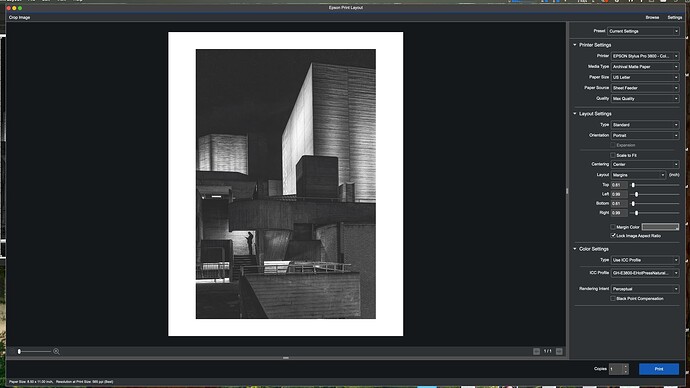
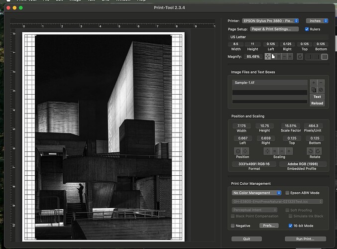
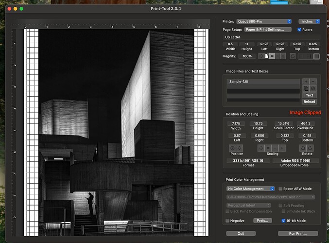
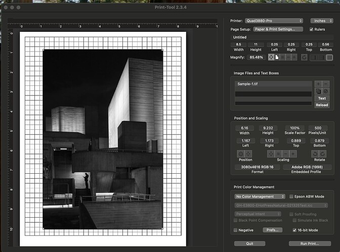
I’m attempting to compare a Piezo print on an Epson 3880 compared to the same print on an Epson 3800 with Cone Ink. The Piezo printer is linearly calibrated to 256 points. I generated a custom icc profile for the Epson 3800. Before I could print the sample on the Piezo printer I noticed an issue. I used Epson Print Layout on the color printer and Print Tool on the Piezo. The Epson Print Layout displays and prints the entire image. When I use the Print Tool I notice that it clips the file and doesn’t print the entire picture. Both pieces of software is using the same .TIF file.
What am I doing wrong?
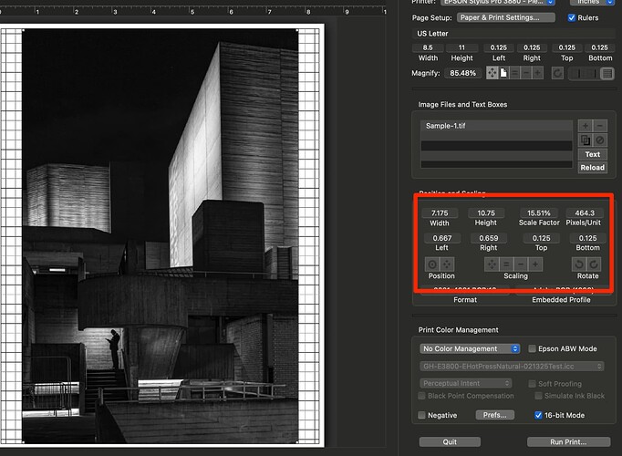
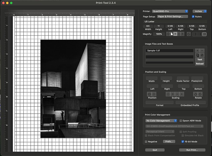
Here are the pictures of each…
I couldn’t begin to tell you about EPSON print layout as it is not a software I have used or would use to print with color management, etc…
According to QuadTone RIP it can not print the bottom.56 inch of any print layout or .25 top and sides. So that is the limiting factor there…
How EPSON software behaves I’ve not a clue!
How do I print the entire picture on Print Tool? Why doesn’t Print Tool throw an error when they are not able to print the entire picture?
(I’m not looking for advice on the Epson software, as it appears to be working as expected.)
Just scale it use the scaling and size tools.
I don’t mean to be difficult, but already I tried that…
It is still clipping…
I can see what you did because there is no data there. And do you mean by clipping that what you see above is not what is coming out of the printer? What do you exactly mean by clipping?
What I mean by clipping is that there is a message that comes up initially that says the image is clipped. (See below) Then I scale to fit the picture in the space and the message goes away, however the image is still clipped. What I see come out on the printer is exactly what I’m seeing the screen. It’s clipped from the start.
The reason it comes in clipped is because its size that was specified in your imaging application was quite large in order of some 50inches or more so it imports it fitting it to an artificial constraint of about 15.5% of the original size and alerts you that it is being clipped because your page setup does not match the minimum margins as required by QTR. You could create a custom setup for an 8.5x11 page and use .25 margins sides and top and .56 margin on the bottom - in which case it will still import it and shrink it to the constraints of your custom page setup. But as it is you are going to lose more than a 1/4" of the bottom and 1/8th inch sides and tops because of the minimum margin requirements of QTR which I mentioned earlier and am mentioning again.
So you are scaling it to your artificial constraints of 0.125 page margins rather than the QTR minimum requirements.
Does that make sense?
So, it the file size that killing this…
I notice that the ppl for the cropped image is 464 ppi with print tool. With Epson, it says it is 514 psi. I’m able to get to 2440 ppi on the Epson, which is the max ppi for the printer. (It actually goes beyond that… but that’s Epson.) If I scale down the clipped image, I’m only able to get 720. It’s stuck at 720 ppi.
What bothers me it that this image came from my Q2M which is ~47Mp. I decided to replace it with a M11M, which is ~60Mp. (Which is on order.) The problem will only get worse. When I look at both images with a loupe, I see that image is not as crisp with piezography than it is with the Epson driver… which is most likely due to the loss resolution.
Why does Epson seem to be supporting more than 720?
Its not the file size. It’s your page setup.
You can print very high resolution file sizes. In fact, with QTR you can print at much higher resolutions than the EPSON driver. But none of that is your issue. I was just commenting that your file image size INCHES dimensions are quite large if at only 15% it fits in a letter sized page setup. 6,000 pixels can be described in your image size app at 300dpi to make 20 inches or 600dpi to make 10 or 1200dpi to make 5 inches. The resolution is the same but the inches dimension is not. Your native inches dimensions is not too large by any means. PrintTool will fit it into the page setup.
It is solely your page setup which is causing clipping because you will not adhere to the QuadTone RIP requirements. If you did, the image would not clip.
I’m not certain where it is actually documented. I never saw it in the QTR tutorial and the author of QTR hasn’t really published any documentation about his software - at least not as far as I recall - but it is one of those things that every user eventually figures out about QTR. I have noted recently a user experience an even larger margin at the bottom and experiencing banding further than .56 up… so it may also be related to OS X permeations.
EPSON dithering is very sophisticated in that it is averaging in several axises but when it gets to the margins it does not average in the margin to the dithering. QTR does… so one stays away from these sides and top and bottom limits.
For those who really need to print further they tape leaders on to the papers and expand their page setup to compensate.
I turned out doing a slightly different method. I used the same dimensions that the Epson print used and used the same resolution also. I got 100% scale factor with the no errors.
That brings me to the next issue. I had linearized out to 256 points with piezo. I was hoping to use that curve when building a icc profile. I saw the methodology using the piezo professional but when I used it, it seemed to give a bad profile. Instead I used Walker’s method of taking a 21 step target and printing it with the 256 step curve. That seems to give me a icc profile that worked properly. However, when I compare the output of the cone color against piezo, the piezo is somewhat lighter. I was hoping for something closer. Does using the piezo pro tool produce a better profile than Walker’s method? Do you also see a darker print with the cone inks than the piezo?
Piezography is more linear than using the EPSON printer driver. So the print is more open especially in the shadows. In Piezography Professional Edition Toolkit you may wish to explore Contrast Tweaking especially if your Piezography prints have more shadow detail than your display shows you. Alternatively, you could purchase a hardware calibrator type display and use Soft Proofing. You do not need more than a few steps to create an ICC profile. The 21 steps is enough to use as a Soft Proof. Make sure you follow the Soft Proof instructions concerning RGB numbers.
I bought a I1 Pro 2… that is what I used for all calibration and linearization. I use a BENQ SW272U and have it calibrated and I do soft proofing. When I soft proof for the piezo or use any of the color profiles generated by the standard I1 calibration workflow It seems to be right on. (Or pretty damn close) The workflow for the color ICC target was 4 pages.
What about black point? I didn’t see it on the piezo printer. Could make a difference?It seems that if everything is calibrated correctly, they should match. This is the first time that I have used custom profiles. What surprised me was there was not much difference between matte papers. The differences were very subtle. When I use the supplied profiles, there were much more of a difference. When thinking about it, that should be expected if I’m profiling correctly. Am I correct in my thinking?
You can’t make the Epson RGB driver print linear unless you do some severe alteration of the ICCs you produce and there are ICC user groups that you can find support from. Or you can study the ICC format and find out how to alter them yourselves. Otherwise all you can do is correct the color output of the Epson driver and ICC profiling does not make every media match one another. The obvious is profiling an uncoated warm tone washi and a high achiever like Canson Arches 88. Will be like salt and pepper in terms of output but the ICC will at least correct color balance.
But you can make the QTR driver print with any gamma you want by using color management while printing from Print Tool and using an ICC designed to change gamma, or by my previous suggestion to you to fundamentally change how PPET produces curves with Contrast Tweaking.
It is easier to match Piezography to the Epson driver than visa versa. But profiling the different printing methods to their basic standards is not going to make a match between Piezography and Epson output. The main difference being the extraordinarily large amount of Piezography shadow detail admittedly much more than most displays can display but is there in the file.
An easy experiment for you is printing your custom curve but setting Print Tool to Print Tool manages color and selecting the Piezography matte icc in the ICC list. That will change the gamma of Piezography from linear to something closer to what you get from the Epson driver and perhaps better suit your aesthetics.
However you could also, because you have a hardware calibrator display, simply soft proof and adjust your image to the way you prefer. Then print the standard linear way and by doing so you define how much shadow detail you prefer.
There are many different ways of using the system. Soft Proofing especially useful for those steeped in alternative processes in which the output has so many different expressions and they want absolute control. Contrast Tweaking for those who prefer to rid the shadow detail for a more darker output they’re used to or want to dial in. Printing with Color Management a quick fix that satisfies most who do not have the calibration to preview successfully.
And along your journey you’ll find that there is even a PPET tool for matching other output systems. And if you regularly blend or split tone two or three curves a way to combine them into one.
J
You say that I can’t make the Epson icc profile linear, but it seems to be already linear. When I compare the 21 step target from both printers it’s seems to be the same. When I soft proof a picture with either of the profiles, I see no change. I created the profile for the 3800 with cone color inks using the standard i1 Profile 2 process. The 3880 profile was create from a 21 step target via the method outlined by Walker. So from a icc profile it would seem they should print identical, or at least close to the same. They are not.
What am I missing?
Take the 256 target and print it on color inks and see if it looks same as Piezography 256 target. Print without ICC with Piezography just the curve and No Color Management print tool. With Epson color print via your ICC. Let me know if you can discern bottom 16 shades as same with both systems.
I want everything the same except the printer, so I’m going to use Print Tool for both. I want make sure I’m doing this right…
I’ve selected Print Tool Managed for color and then I’m using the icc from the color profile I created for the 3800. As for the driver, I’m using the same settings that I always use. (Archival Matter, 16 bit, 2880…)
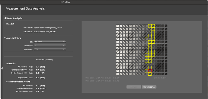
I’m going to measure both targets once they dry for a day using the I1 Pro 2.
Here are the results…
I have the .pdf with the results. I’m unable to load it. If you are interested I can send it to you.
