After installing the inks on the 9900 I have proceeded to linearize Han Photo Rag. I remapped the original curve found on the piezography curves for K7 and 9900, so that I could bypass the LC, LM and Or channels. I took great care to do so. I checked by printing a calibration 10 ink image, seeing that indeed each shade is in its good place.
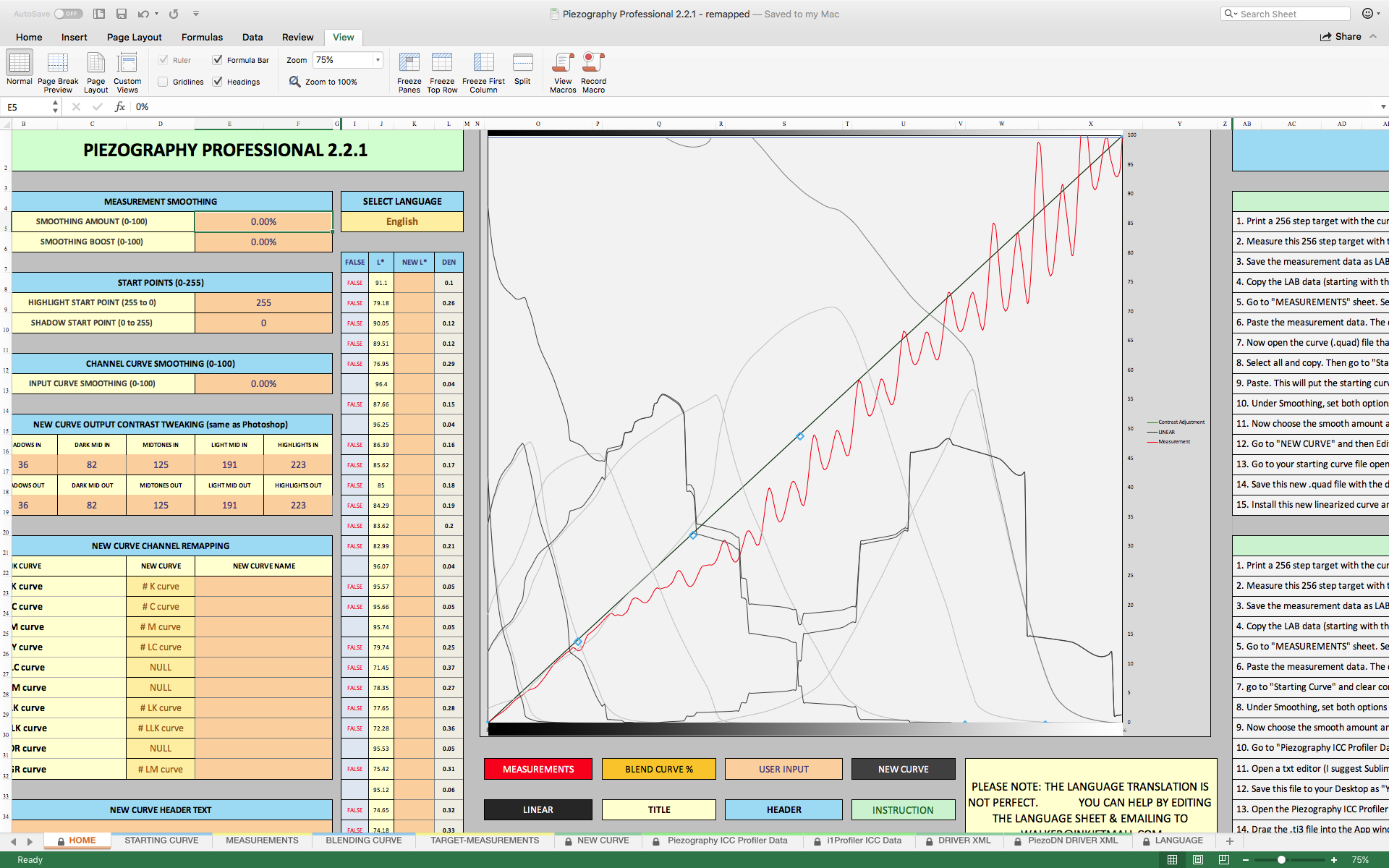
What happened puzzled me a bit. I have printed the 256 patches target, measured with the I1pro v2 in M0 mode (single pass). The results are extremely jagged, with many many (many) false values. See results attached.
Interestingly, on the target printed I see no banding, no strange artifacts, and indeed the patches look nice… I guess this kind of wavy behaviour is eventually not easy to spot without measurements, anyway…
On the screen attached, I have kept the smoothing and boost values at 0%, so that you can see it in all its “glory”. The waves remain quite a bit even at 85%. This is even more than I usually got when calibrating Digital Negatives…
I guess something here is wrong. Any idea about what could be the culprit here? Is it normal?
I also see that the channel curves appear very jagged too! However, I started using a curve taken from the Piezography folder (HanPhotoRag K7 9900) and the only thing I did was remapping the channels, as can be seen on the other image attached.
Thanks in advance for your help with this.
Regards,
rafael
Hi,
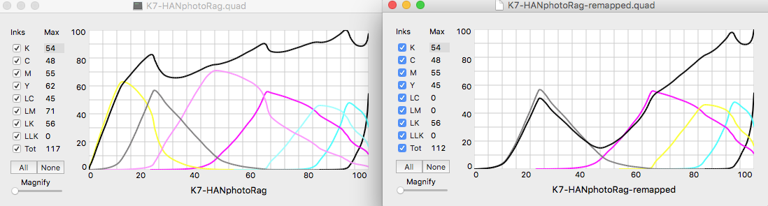
I think you have somehow messed things up with your remapping. I only see 5 inks on the right graph which means you are missing two inks. The first sign that something is wrong is that the solid black line (which represents the totals across all used inks in the quad file) is not identical to the original quad file. If properly re-mapped, you should see identical curves but just some of the individual channels would have different colors than in the original quad file.
Hi Dave. Thanks for chiming in.
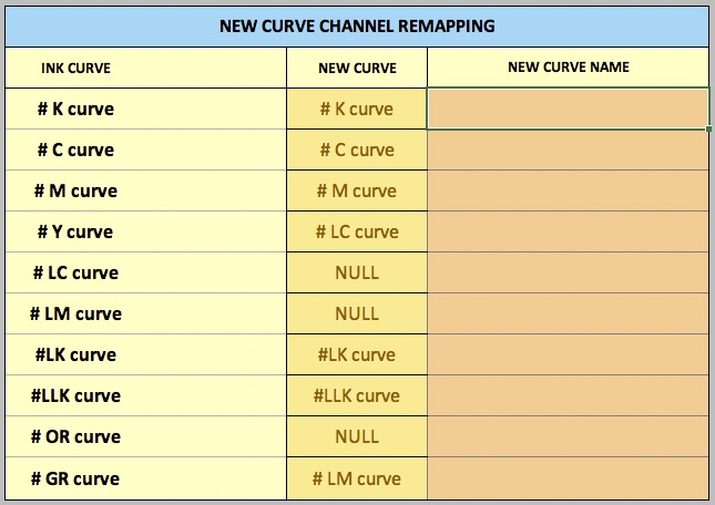
In fact, I have followed the instructions I was given (which make sense to me) in order to do the remapping. I have the LC, LM and ORange not working. So what I did was this remapping:
I am using K6, not K7. I have not seen any curves for K6 in the Piezography folder, so I have remapped a K7 curve for 9900 (photo Rag Han). I loaded the original curve on the Starting Curve, cleaned the Measurements and Copied the New Curve values into a new remapped curve. I am copying the remapped curve (also smoothed) to this message as attached file.
On that new curve remapped the GR channel is working, as you can see in the remapping chart of PPEv2. The Green channel does not appear on the curve diagrams given by QTR-CurveView, I suppose because on the original curve it was not used? That might be why the total ink is not right? In any case, looking at the remapped curve numerical values with the text editor (that I attach to this message), it can be seen that there are values for the Green Channel…So I guess it is working?
The other missing inks are the shade 7. I am not using it, basically I am working with a K6 system, not K7. I have not seen any K6 curves on the Piezography folder…so I took a K7 curve instead. I suppose that is right?
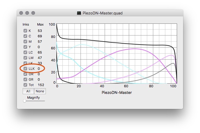
Then, the LLK has zero value, both in the original and remapped curve (since LLK remains LLK). That channel is for GO, so I guess that is why we do not need it…
In other words, looking inside at the quad curve I see it looks logical: The LC and LM and OR are zeroed, then the Yellow gets the values from LC and the Green gets the values for LM. Green does not appear on the graphs however, even if the file has values inside… No idea why.
Am I doing the remapping right?
Is normal to have such a wavy response in the measurements of my target?
Once I have remapped the curve and I want to linearize it in different stages, I suppose I must use PPEv2 with the “New Curve Channel Remapping” set back to normal? or should it leave it still in the “remapped” configuration? Or is it just the same?
Thanks in advance for the help. I am stuck at this!
First thing I can think of is that QTR-CurveView does not display OR and GR so it is pretty much useless for visualizing in your situation. That is why it appears to be missing the remapped LM>GR curve. Use the PPEv2 graph instead even though it’s not color coded.
Second, the absence of shade 7 (Y channel) would surely have an effect in the remapped curve. I doubt changing from K7 to K6 is as simple as eliminating shade 7 since there is substantial overlap among channels. Compare a K6 curve to a K7 or the one you modified from K7 to K6 to see what I mean.
Third, once the remapping is done it’s done. Any further work with or on the curve will start with the Channel Remapping tool reset to normal, otherwise it will remap your remap which I think is part of what we see in your PPEv2 graph, along with the rollerocoaster wobbles.
I redid this with a K6 curve from the folder Walker referenced and the remap is a perfect match to the original. The curve you uploaded is similar to those in the K6 folder, but with less overlap and a bit thin on shade 6 at the right edge.
I am surprised that you say you don’t see it in the print. Those large wobbles should be obvious. Could there be a malfunction of your spectro as well?
I would guess that if you redo this with a K6 curve from the HD folder the outcome will improve.
As always, I could be mistaken about any or all of the above.
I have done what you mention on the K6 curve, and printed the target. I will leave it overnight to dry and read it tomorrow. I have to say the target looks much better than the other one…
Because I am using the conventional blacks (not the HD), I stayed away from the curves folder “HD”. The idea the K6 curves might be there never crossed my mind…
On another point, for what I have understood, these K6 curves do not use GO at the same time a gloss print is done, but one needs to put the print back on the printer, and run a GO curve that will only apply that liquid. Is this correct? If yes, is this needed for printing digital negatives? I remember when using Piezo DN that the GO was applied at the same time, so I guess those curves are still applying GO “on the fly”.
Does really GO make a difference for gloss prints and for digital negatives? I ask because I see it would be possible to sacrifice GO for one of the blacks, and use a P2 system for both gloss and matte. Would that sacrifice be stupid? (I can always use the BK switch, after all).
So it turns out Roy posted a new version of CurveView on Jan 1, 2020. It has the ability to show all channels of 10-ink printers, and is also 64-bit for those who need that compatibility. You can download it here: Dropbox
Unzip the download and replace the copy of CurveView that is in your QuadToneRIP folder with the new version.
My memory about PiezoDN curves no longer using GO was also correct. Here is an example from the folder Curves>7900-9900-PiezoDN:
I don’t make prints on Glossy paper so I can’t speak to that question. I suppose you could use that channel for shade 7 if you want to stay with a K7 setup. I haven’t missed shade 7 with my P2 setup.
You always had a solution (that works) for everything! I have still to see when “you are wrong”
I tried with the K6 curves and yes, the linearization looks way way better. Doing a second now.
Interesting, I had perfect smooth tones with the Hahnehmuhle Photo Rag 308 gsm, but a bit of dark lines of banding on the darkest area with the Hahnehmuhle Photo Rag Book and Album which is 210 gsm. Both papers are using Media Setting of Velvet Fine Art (according to HN), but I guess that due to the fact the Book and Album paper is way thinner, a different setting of Paper Feed Adjustment might be needed… In any case, I do not think that will affect the linearization. So I will get to the end of it, and then play with different values for the Feed Adjustment. By the way, the same thing happened to me when printing targets with PiezoDN for negatives. It seems that the Paper Feed Adjustment parameter might be more important than we think to guarantee smooth printing. That being said, it seems to me that that little banding that can be seen on patches of targets (uniform tones) does not get visible when printing real life images (where tones are never perfectly homogenous).