Human innovation at its best. 
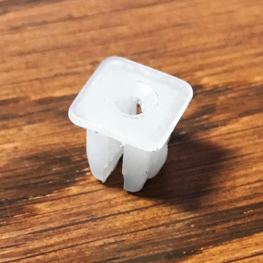
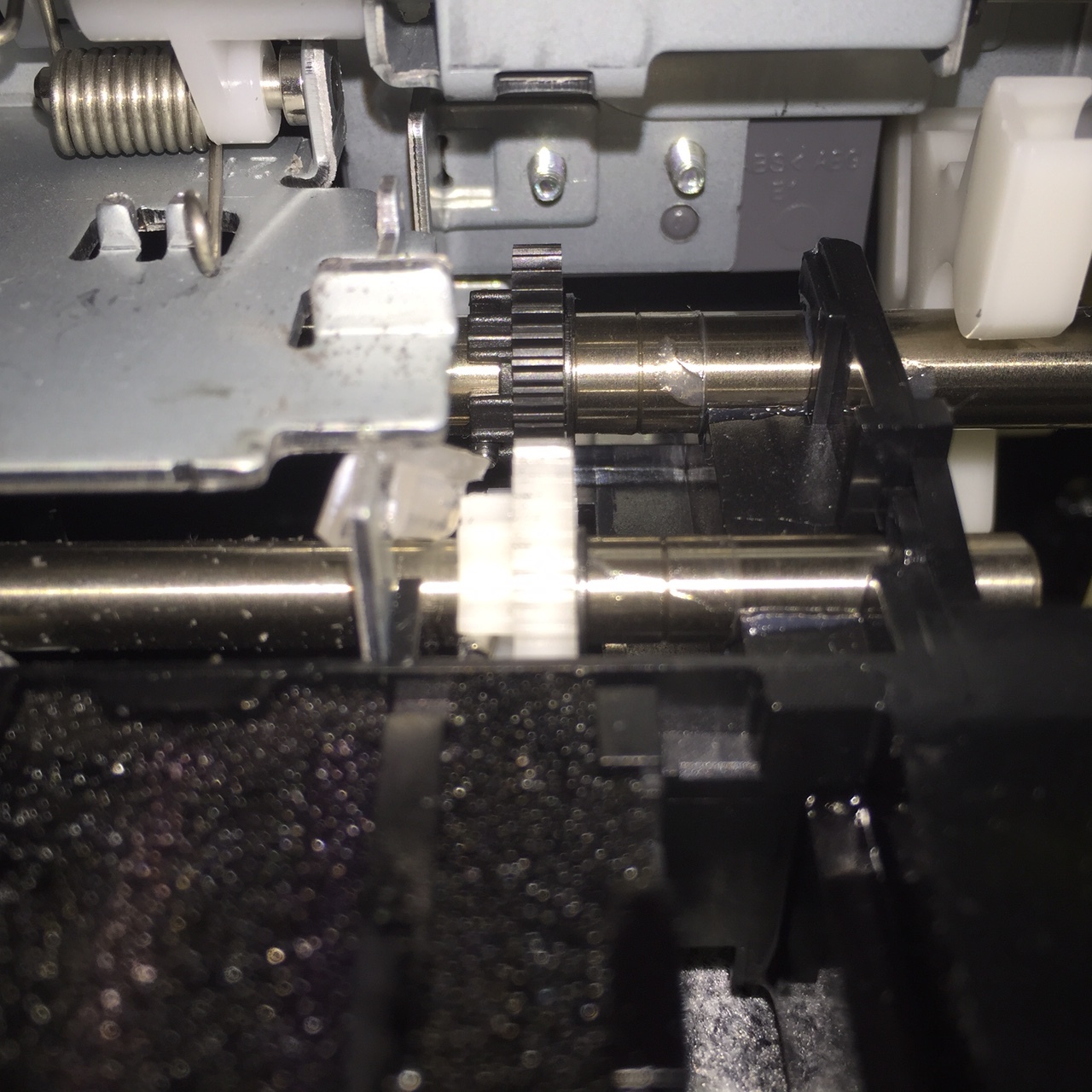
Good timing to revisit this topic. As I mentioned in another thread about a month ago, my first 1430 suddenly threw an error where it wasn’t recognizing the home position. I wasn’t able to solve the problem, and instead bought a refurbed one from Epson for $200. This time, rather than pull the star-wheels, I decided to try Don’s method of lifting the star-wheel frame outlined here. Looking thru a box of miscellaneous doo-dads collected over many years, I found this little thingamajiggy, which fits perfectly over the metal tab to keep the frame in the lifted position.
[attachment file=26235]
In a private conversation with Gareth Jarvis, I posted this picture, which he was able to identify as a clip for attaching interior trim panels in cars. Here is an eBay link. They may be available at auto-parts stores, but I haven’t checked yet.
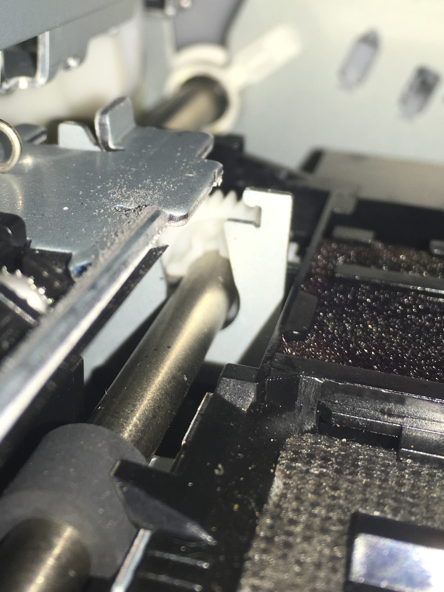
I also found that sticking the iPhone down into the printer lens first (upside down) worked really well for photographing the hard-to-see spot where it goes.
[attachment file=26236]
[attachment file=26237]
[attachment file=26238]
Now, all this is fine for avoiding marks on the film, but those star-wheels do have a functional role in these vacuum-less little printers, and that is to keep the paper/film at the proper distance from the head. With no star-wheels being used at all, it is possible that the head may strike the paper/film edge or rub on the surface. I think this is what Shane Booth alluded to earlier. I haven’t had a problem with film (knock-on-wood), but I have with plain paper used for nozzle checks where the head rubbed the paper leaving a smear of ink. My solution is to let the star-wheels down when doing anything other than printing on film.
Another reversible option would be to remove the plastic pieces that snap into the frame and simply leave them off, without removing the wheels from them, so they could be reinserted if necessary.
Keith makes several valuable observations about this method to lift the pin wheels up out of the way, especially that it is so easily reversed. I have my own caution about not trying to print with the built in border but to print with clear edges. This will keep the printer from continuing to print at beyond the end after your image where if it continued printing the black border the Pictorico will come free from the back feed rollers immediately curling such that head crashes are guaranteed. This is true no matter how you get rid of the pin wheels.
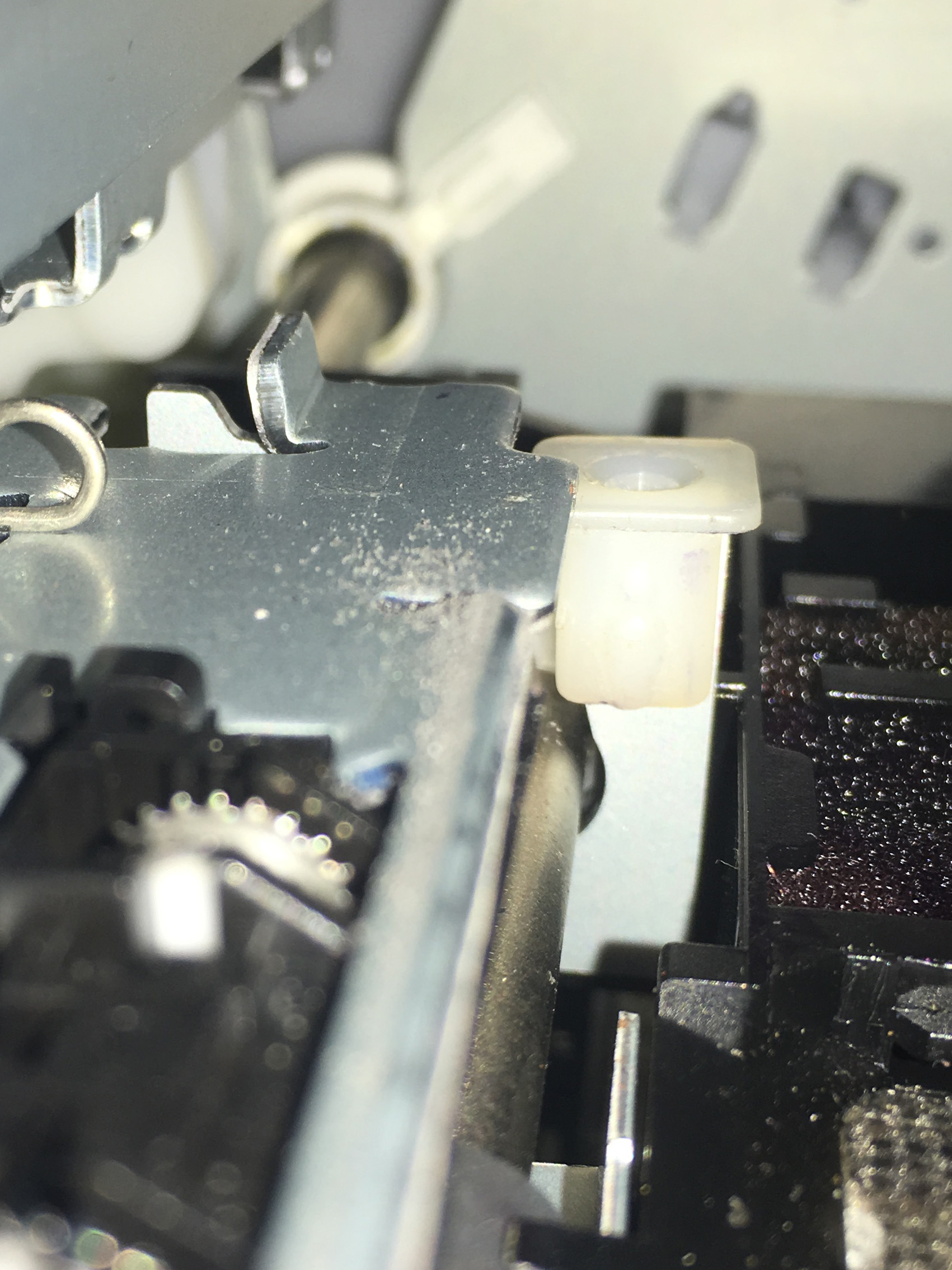
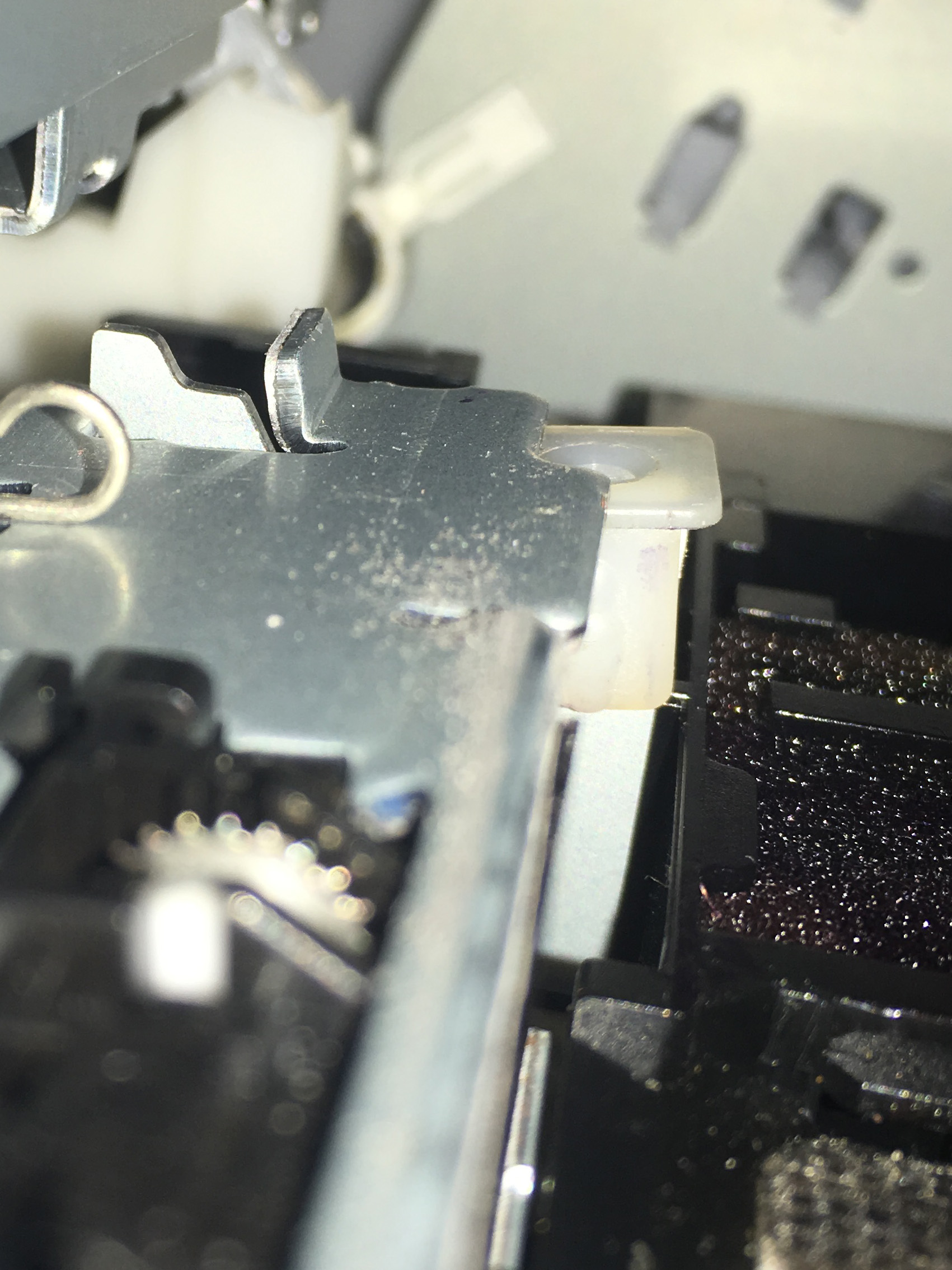
I place my spacer on the left hand side of the printer where the longer tab allows the channel material to sit below the lock tab creating a minimal lift to the pin wheels. Both placements work.
I think mine is in the same place, Don, on the vertical tab at the far left. But where mine sits on top of it, it look like yours is behind it (on the side towards the front of the printer). I haven’t tried printing close to the film edge (left/right) so maybe that’s why I haven’t had a problem with it. I agree - leave plenty of space around the image.
You are correct, you are on the left, my misread of your photo, plus the left hand side is far more accessible.
A question for Don and others who’ve used a piece of plastic to modify the tab on the left side of the printer.
Do you have problems with the star wheels on the right side? The piece of plastic is good for keep the star wheels up on the left, but the tab engages on the right and forces the wheels down on my printer. The result - no star wheels on one side of my negative but they are faintly there on the right. I tried to get at the tab on the right but haven’t found a way to insert a piece of plastic there - the ink cartridge is in the way…
Thoughts?
I suggest simply printing with a larger sheet of film and letting the right-side star-wheel stay in. it’s good for continually alignment and also to keep the print-head from hitting the film.
-Walker
You can raise the left side a touch more to remove the far right pinhole marks, BUT I agree with Walker as it seems you are printing near edge to edge. If you are printing edge to edge it is recommended you let the far right pinwheel guide the negative and keep it down on one side as the Pictorico can curl up with that much ink and cause head crashes on the edge of the film.
There has to be a way to safely remove these wheels and assure a safe and trouble free path. You folks at inkjetmall don’t have a slick fix for this? As someone starting out with a brand new 1430 I am a bit hesitant to go ripping parts out that may cause greater problems.
This is a slick fix and doesn’t involve ripping anything out or making any permanent alterations to the printer.
By the way, for reasons I don’t know, my 2nd 1430 does not leave star-wheel marks at all. So I suggest you try it first to be sure you really need to do something before doing something you may not really need to do. (That was a fun sentence to write. ;))
Thanks Keith. So probably saved me a good bit of work. I ran a sheet of plastic through just using the epson inks and saw NO wheel marks at all. Will now load the correct inks since I know it all works. ONE OTHER QUESTION!!! I am rather new to this. Where can I find the curve to use when making a negative to print on Silver Gelatin??? Any help would be great. There is a lot of info around this thing but it is a bit overwhelming! Dan
Currently there is no silver gel curve for the 1430 however it is fairly simple to linearize the master 1430 curve for silver following the instructions in the deluxe manual.
-Walker
Dan,
TIP: It’s really important to find your optimum exposure time using an unprinted strip of Pictorico Ultra Premium OHP film when you make step exposures on your silver paper. DO NOT BE TEMPTED to use a Stouffer strip as it will introduce a density in it’s film base that will throw off the timing calculation. Using the Stouffer in combination with the Ultra Premium OHP really compounds a timing error.
Later after you created your silver curve, when you are printing your negs on Ultra Premium OHP its clear film base is your dMax on the silver paper - and that is why you use it initially to determine exposure time.
best,
Jon
Jon,
Thanks! That takes me back to the days of Fred Picker when he talked about the “PROPER PROOF”. Good thing that works because I haven’t a clue what a Stouffer Strip is. So if I at least start to read this right. I start with the generic curve(not PL/PA and not the tintype one). Print a negative. Make a Proper Proof. Let it dry. Measure it with the Color Munki. Open Something in Google…do I need to purchase something else other than the PiezoPD? Linearize the 51 step. Print Neg. Make Proper Proof. Dry. Load into program. Print 129 Step. Make Proof. Dry. Linearize. Print. Make Visual Check. Load profile/curve and go and make GREAT Negs! That about have it?
in so many words yes… but we use more words in the manual! 
Also, you don’t need to use Google (that is just Piezography Professional Edition). The CGATS Smoother Tool is all you need and that comes with PiezoDN and is in the >Tools folder.
best,
Walker
Jon,
That’s what comes from growing up in a military household! It is really exciting to read the manuals because you get to see the level of control that is possible with this system. When I have completed the process and produced a really good final product I will take the liberty of giving you my thoughts on my experience in finding and completing different operations. I will also have some of my students (ages 15-18) give feedback on their experience. It appears a bit overwhelming at first but on a second read through it starts to clear up…not really sure it would be possible to make it easier but if there is a way we will try to find it. Of course feel free to ignore all of this!!!
All the best,
Dan
- I posted this earlier but it’s not showing up on my computer. Apologies if this is a duplicate. *
Ha! I agree with Jon completely about the importance of finding the optimum exposure time - the minimum time to achieve maximum black - so many people have problems due to overexposure - but disagree regarding the use of a Stouffer tablet. I’ve written about this in detail more than once, and probably on this forum somewhere, and with illustrations, but the PROPER use of a 21- or 31-step Stouffer tablet makes this easy and accurate. The issue of the film base density is is almost negligible at 0.05 (log density) which is 1/6th of a stop, but is simple to factor out multiplying your result by 0.89 which is 2 raised to the power of the desired change in stops - in this case -1/6 or -0.167
The problem is that it is very difficult for our eyes to accurately interpret tiny changes in density at he black end of the tonal scale. This was driven home to me 20-some years ago in a sensitometry workshop taught by Phil Davis, author of Beyond The Zone System, and a very fine alt-process printer himself. We were given a set of 100 or 101 darkroom printed squares of pure tone from paper white to maximum black and asked to put them is order from white to black. The midrange was easy as you might expect; the extreme highlight slightly challenging, but everyone got it right; but the shadows above 90% were impossible to judge accurately or consistently. None of us got the deep shadow range ordered correctly, and moreover each of us had a different order!
With a 21-step (what I use) the difference between stops is 0.15 or 1/2 stop. You find the shortest exposure time that results in steps 1 and 2 merging to black, but still maintains visible separation between steps 2 and 3. Then you multiply that time by the appropriate correction factor(s). In this case 0.707 (-1/2 stop) for the distance between steps followed by the film base correction for the Stouffer of 0.89 (-1/6 stop). For example, if your empirically determined exposure time as described above is 10 minutes, your adjusted exposure time will be 10 x 0.71 x 0.89 = 6.32. Simple and accurate.
Of course you can get to the same result eventually by trial and error, but at least for me this is faster and never fails.
I have little spreadsheet for calculating all sorts of exposure adjustments if you are interested.

OK…once again I am at a standstill. Followed the directions to the letter as far as installing CIS on Epson 1430. Reconnected power and ALL ink lights are lit. Troubleshooting guide gives me two options. First one…move head to ink change position, press white button for several seconds, then press ink button to move head back to ready position…NOTHING. Second thing…remove all ink positions and reset in head. Removed cartridges and reset in head. Pressed down so that all cartridges are fully seated. Not sure how carts LOCK in place because they simply press down. No click as in putting in separate Factory carts. Result…LIGHTS still on. Turned printer off and restarted…SAME RESULT. Went into Photoshop to do cleaning…Shows ALL carts not recognized! This is reason why I have never liked CIS!!! Sure there is an answer. Don’t know the answer. Would like to know the answer because I am excited about getting this Puppy purring. Right now I have a rather expensive and not really attractive conversation piece sitting on the desk! HELP!!! Thanks!
Dan
Dear Dan. This should really be on another thread, but in short, you gotta press down pretty hard. Much harder than you would think. Then they will lock in place (lock tabs click under the top rail of the cartridge bay).
best,
Walker