Curve for Carbon Transfer

Hello Walker and forum
I am working with a client who is making Carbon Transfer prints.
The negs are too dense currently when using the supplied ‘master’ curves.
Obviously we need to create a new curve with ink limits.
My question is whether there is recommended starting curve for DN’s that will be used for Carbon Transfer printing?
And any tips or tricks from anyone who has gone down this road?

Using PiezoPro inks in a 3800

Thanks

Instead of limiting I suggest “tone tuning” the curve just way darker in PPEv2 (so not limiting ink just making the lighter inks reach further into the mid-tones and highlights)

-Walker

Thanks Walker let me try that

Hi Walker

Struggling a bit to get a decent neg to use with a Carbon Transfer print.
Neither myself or the client have much experience with Carbon Transfer and its a steep learning curve for both of us.
Above, you recommend “tone tuning” the existing curve. By this do you mean Variable Ink Limiting? There is silent short tutorial on the Piezography website that says “full tutorial coming soon” No chance that full tutorial exists somewhere else? And is this the right thing we should be trying

What we are struggling with is that less than 50% of tones are printing. Shadows and mids print, but then as tones lighten the impression degrades and tapers off drastically

Any help would be great!

please post screenshots and photos.

The more info the better.

thanks
-Walker

Thanks Walker
My client lives in the country and only comes in to town periodically so its a slow process.
Initially we tried some existing curves but they all proved too dense.
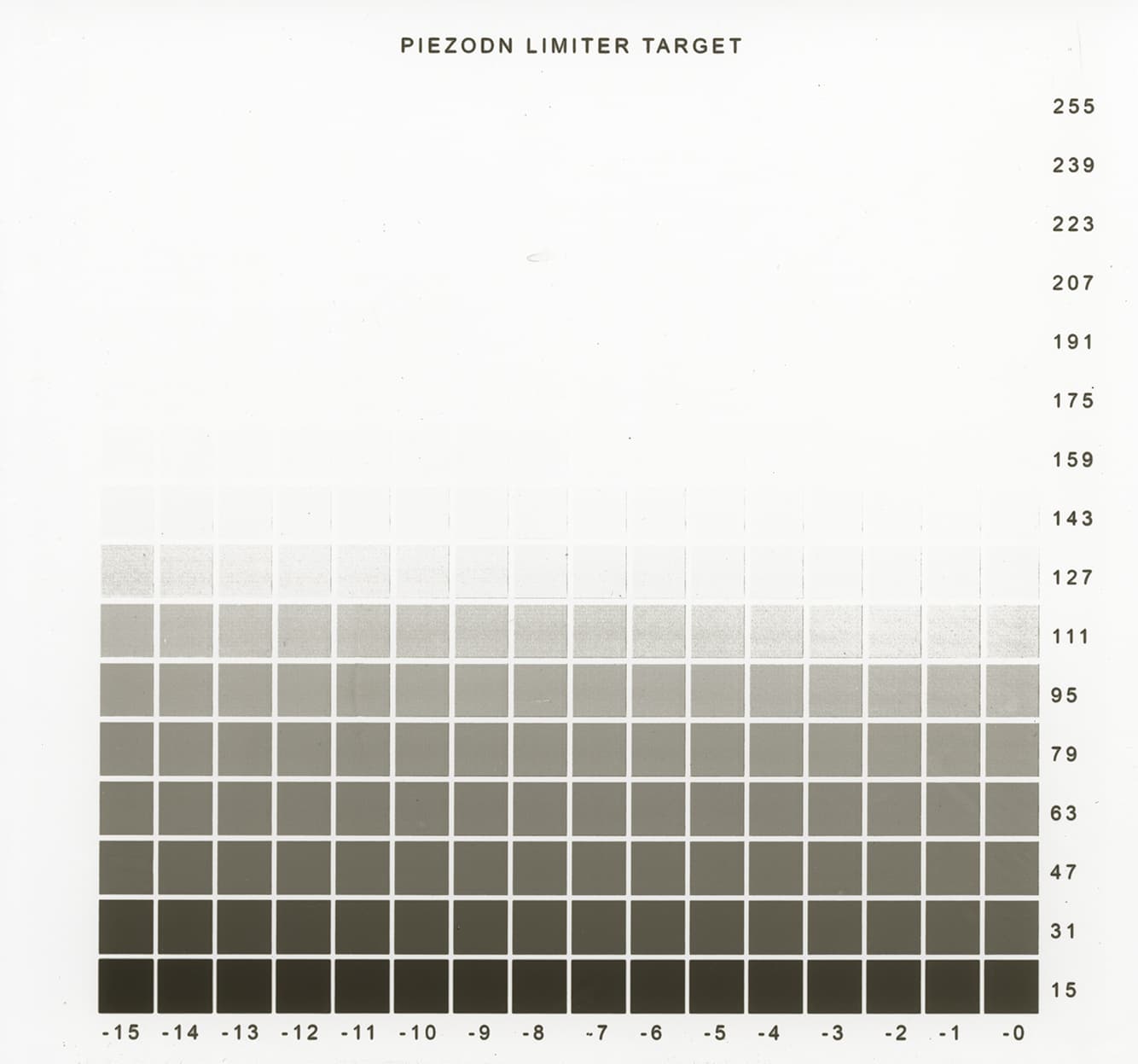
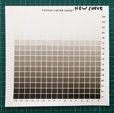
Then, following the Piezography Manual, I printed an Ink Limiter chart which he then took with him and worked with, following the manual instructions about trying to find a ‘ink limit number’
I received an email from him today which says…

1. I prepared 3 different emulsions, each with a higher pigment concentration:

> (#2) 20% weight of gelatine

> (#3) 30% weight of gelatine

> (#4) 40% weight of gelatine

2. I did a minimum exposure for maximum density test on each emulsion. In each case, density stopped increasing around 8 minutes of exposure.

3. I printed the negs with each emulsion at an 8 minute exposure.

…First observations as I developed the prints was that less than 50% of the both negs rendered tone.

In other words, shadows and mid-tones print, but then as tones lighten the impression degrades and tapers off drastically.

There was a marked difference between the "Print Out” neg versus the “Master” neg. The “Master” neg performing better.

In my opinion finding the limit number as described in step 8 is maybe a bit tricky and might require more of an informed lucky guess than what they suggest, as the highlights of the carbon print behave differently than platinum for example.

What I mean is, at a certain point in each print the shift from dark to light between the squares change drastically.

This suggests that we might have to disregard the lightest tones in the print and maybe choose the last square in the print that appears to perform as it should

I’m thinking that maybe the best course of action is to:

> 1. decide on two limit numbers: one as they suggest and one guess from our side.

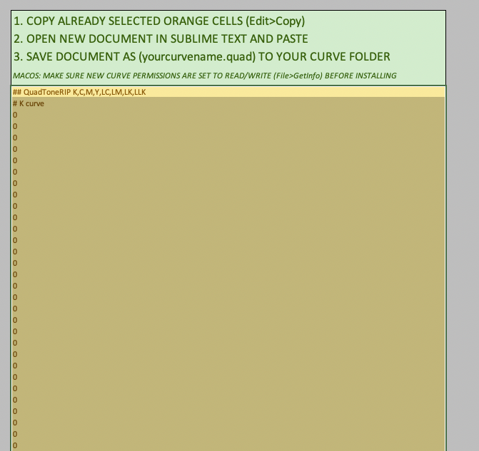
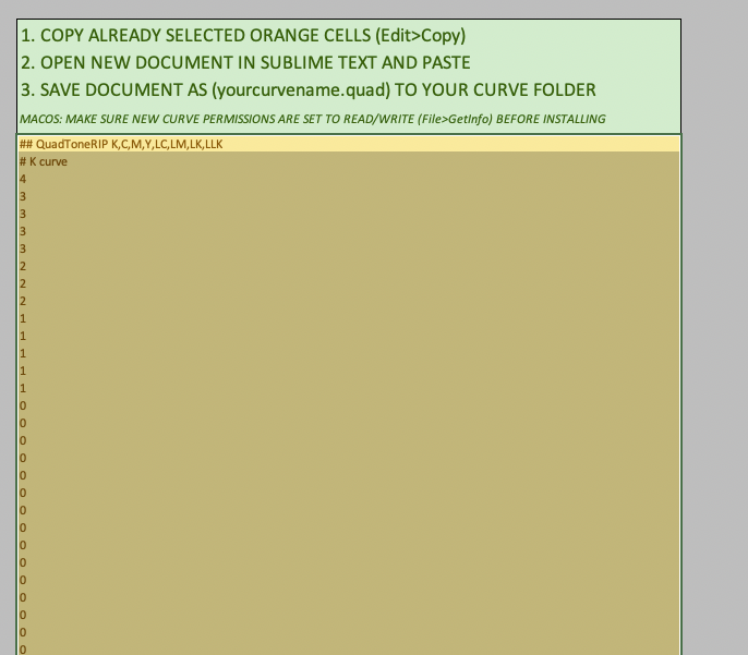
> 2. Print 2 new negs: each with a new curve applied based on the limit number we decide on.

> 3. I print the 2 new negs in studio using the same emulsions.

> 4. We get lucky and the problem is solved. haha.

He is coming in to town tomorrow
What screenshots would be helpful?

Thanks

Please provide screenshots of your limiting process.

Black and White start points are actually where you need to limit stuff probably . . .

basically I need to see screenshots of the process in PPEv2 and the resulting target prints.

-Walker

Thanks Walker
Process so far…I opened and printed the LIMITER file using the Pro-PiezoDN-Master curve.
(Also printed the LIMITER file using the PtPd-PrintOut curve but we have decided that the Master curve is better)
Client then determined an exposure time of 8 minutes and then printed the target neg
See pic of resulting print below
As you can see, less then 50% of values are registering visible tone
Please advise as to best way to proceed?

Now we’re cooking with gas!

Ok. So what you’ll want to do is set your white start point to 143 in PPEv2 with this curve loaded into “starting curve.” Make sure there is no measurements (delete whatever measurements are there).

Then copy/paste the “new curve” data back into sublime text and scroll to the top of the K curve. Set the first number to three times whatever it is. This ensure a specular white that can be calibrated.

Then print the 21x16 target for further calibrations.

You have some highlight degradation but I don’t know enough about CT to know how to resolve that bit.

best
-Walker

Thanks Walker!
Setting white point to 143 makes K channel empty (all zeros)

Setting white point to 159 means that there is still something in the K channel

We going to see what we get from that

sounds like a plan

:slight_smile:

Hi Walker
After creating a new curve as described above (setting white point to 159) the results are definitely an improvement. See below

There still seems to be a threshold where at a certain point the neg stops performing as it should and tone falls off quickly. We are still trying to figure out how to get more consistent tone in the highlights.

Any suggestions would be gratefully received

What about blending some of the shadow values from the master curve into the new curve? Would that somehow ‘push’ everything ‘up’, pushing more values into the highs?

image0