Hi Walker,
Can you post that neg?
Hi Walker,
Can you post that neg?
Hi Art,
I saw your similar request to Walker on the other long thread that I was a participant in. I looked for context for it there but couldn’t find any, and figured maybe it was referring to a private message. But now you’ve got me wondering! What exactly do you mean? Post a scan of a neg? A negative is a physical thing, at least in my world, not a digital file. Maybe if you clarify the request you’ll get what you are asking for.
Cheers,
I did clarify my request and Walker said he would post the neg. What am I missing?
Where? I’d like to help if I can.
Hi Keith,
Ziatype Support 3880 Starting September 9, 2016 at 12:44 pm where Walker said “Please upload a jpg of your scanned negative” and then September 10, 2016 at 9:59 pm when he said he would post his…
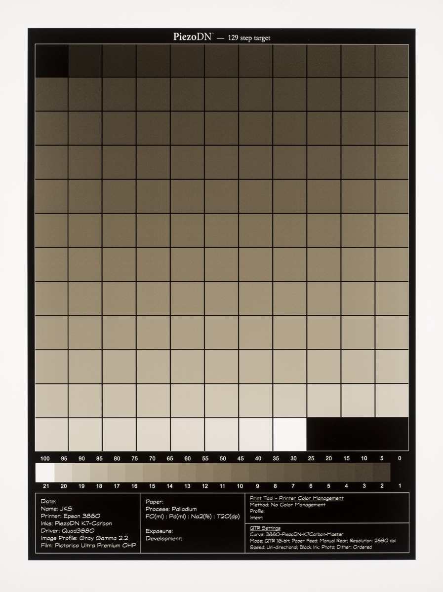
I looked at your scan again. I mean no offense, but that is a really bad scan! I see Walker thinks it was done in reflective mode. Is that correct? A transmissive scan of a negative should not look like that. If it is a transmissive scan, you need to adjust some settings. The patch at top left should not be black. The next one to the right should be white (clear) with no tone but it looks dirty. And most importantly, there should be tone through the entire 129-steps. Around 1/3rd of this is black!
Another observation - what looks like overspray around the edges and in the numbers/letters might indicate that your platen gap is too wide. The edges and numbers should be clean and crisp. I saw something when I first set up my 3880 trying to use the front-feed before I learned how to disable the star-wheels so that I could use the rear-feed without track marks. I only tried a couple negs with the front-feed before switching and did not realize what was going on until later. Rear-feed did not have that problem.
I don’t use the same target since I use different software for spectro readings (SpyderPrint) but it is similar enough. I have to scan a bunch of new 8x10 negatives tomorrow, and I’ll add my PiezoDN-Master neg to the list. It will at least give you an idea of what it should look like. I’ll post tomorrow. Really!
No offense taken Keith! This was a $49 printer/scanner that was used. It was only to show what I was seeing with my i1. The results from the scan and a densitometer had similar results. This is why I wanted to see another negative scan to compare. By the way, if the patch at top left should not be black, what should it be?
Thanks for the platen gap/paper feed tip, I’ll be switching soon.
Hi Art - You’ve still not answered the question about scanning mode, but as far as I know there are no printer/scanner combinations with transparency scanning capabilities, so I guess that answers it indirectly! ![]()
As for the top left patch, when you look at it in the original file it reads 18% and you can see clearly that it is gray and clearly distinguished from the white background. So in the negative it would be the inverse as adjusted by the curve with which it was printed.
By the way, do you have a digital camera and a lightbox? If so, use that to photograph your negs rather than a scanner. It can be as crude or sophisticated as your equipment will allow.
Here is a “scan” of my Master neg made on an LED lightpanel with a Sony aR7 mounted on an improvised copystand. I’ve modified the original target file with a 21-step strip and an area for notes. I do see a bit of the reversal thing happening in the neg which I verified with a transmission densitometer, so it is not from uneven illumination from the lightpanel.
[attachment file=1511]
Keith. Which patches where reversing?
Also, this camera scan has lens falloff on the edge.
W
Walker - I see what you mean about the edges/corners, though I think that would have the opposite effect on the image tones - denser towards the edges, lighter towards the center. But it’s not just the camera scan. As I said in the notes above, I verified it with my X-Rite 361T. It’s definitely not in the original file, so it must be coming from the printer. At least some of the wobbles in the printed targets are already there in the negs. I’ll check some of my earlier 1430 negs over the weekend to see if it was there too. I don’t remember the wobbles being so dramatic, but wrote it off to the weird paper I’m using now. I was surprised to see this on Platine, and more so on the neg.
I should add, I’m not terribly concerned about it since I see no evidence of a problem in actual prints.
The wobbles/reversals are oddly similar to what I’m seeing…But as Keith said, as of yet, I do not see a problem in actual prints.
Thanks Keith for reminding me of another use for our soft-view print viewer!
Walker,
I just looked though my notebook of calibration target negs beginning pre-release in May when I was using the 1430. None of those negs display this strange and unexpected behavior. It began when I switched to the 3880, and looking at those, which begin in mid-August, all of them have it to some degree. Here are some thoughts on possible causes:
Any other suggestions are welcome.

I suggest printing this target at 90 degrees and measuring that. If the wobbles are in the exact same steps than it’s the curve, if the wobbles have shifted by 90 degrees (aka, the top and bottom patches are “lighter”) then it’s in the pressure system of the printer and larger film must be used to regulated pressure at the top and bottom of the print.
That said, Arts luminance shift of over L10-L20 from one patch to another could be a compounded light fall-off of the exposure unit + brush-stroked. The L shift I’m seeing in the scan does would not show in-print like that.
-Walker
Good idea, Walker. I thought of that too after I went to bed last night. And larger film too. And printing the target on paper too. And probably a few other things I’ve forgotten already. I have been using 8.5x12 sheets cut from a 17" roll for calibration tests. I print my image negs with larger borders which may be why I haven’t seen signs of a problem there. As for the effect of light fall off in printing, consider that in a print of the target the darker parts are towards the sides rather than the center which is what we would expect from falloff in the negative. If this is being compounded by the lightsource it is indicating falloff towards the center which is very unusual in my experience. Thinking about that though does suggest something else to try - rotating the negative 90° to the lightsource.
I’ll report back when I have figured something out.
Ok. I just took a look at the 3 129-step negs I made yesterday.
Looking through other targets than the one specifically designated for SpyderPrint, I noticed that most of them are smaller in size, and many are horizontal in orientation. I think both of these factors, especially the orientation, would tend to diminish what we might call the “edge effect”. Since I make my readings manually and freehand (without the guide), I see no reason not to use a different target file. The patch values on all of the 129-step targets are the same and that is what really matters.
I did a validation Piezography print today and saw the same thing in ink-on-paper densities.
And validated with rotated and larger-paper etc. I also see the same thing with it’s newer cousin (P800) in lab.
No other printers.
This is unique to this printer build.
-Walker
Thanks for checking Walker. I guess it’s good to know I (and others who have noticed this) am not crazy. You did it on paper with the same result? I wonder why in all the years this printer has been out no one has noticed this before. Thanks to Art for bringing it to our attention.
All that being what it is, I still don’t think it has a visibly noticeable impact on prints.
<span style=“color: #000000; font-family: Helvetica; font-size: 14px;”>Hi all,</span>
Stefan,
Thanks for the suggestion about adding thin line(s) to the side edges. I think I understand what you mean, but would you mind posting an image to show us.