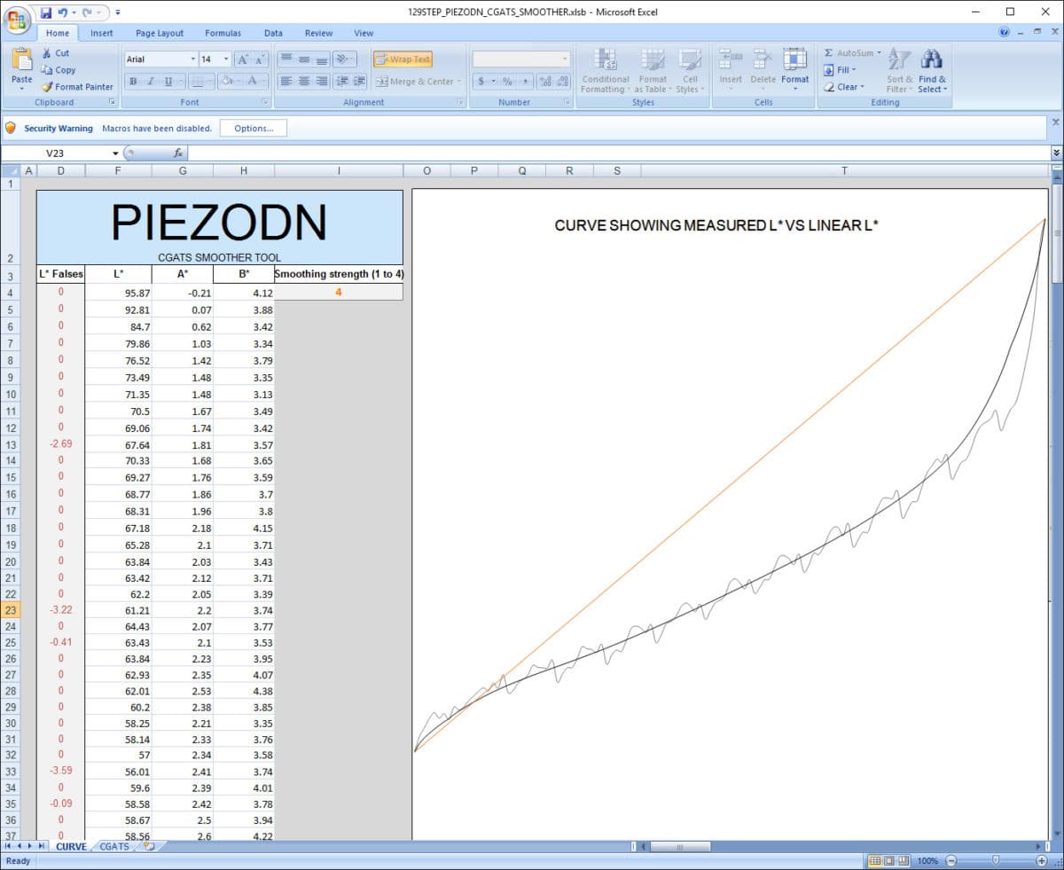
As suggested I’m using the x800-x880-PiezoDN-Master.quad to print on my 3880. I tried printing a “confirmation” print using the linearized curve. It wasn’t linear and well, it just didn’t look right.
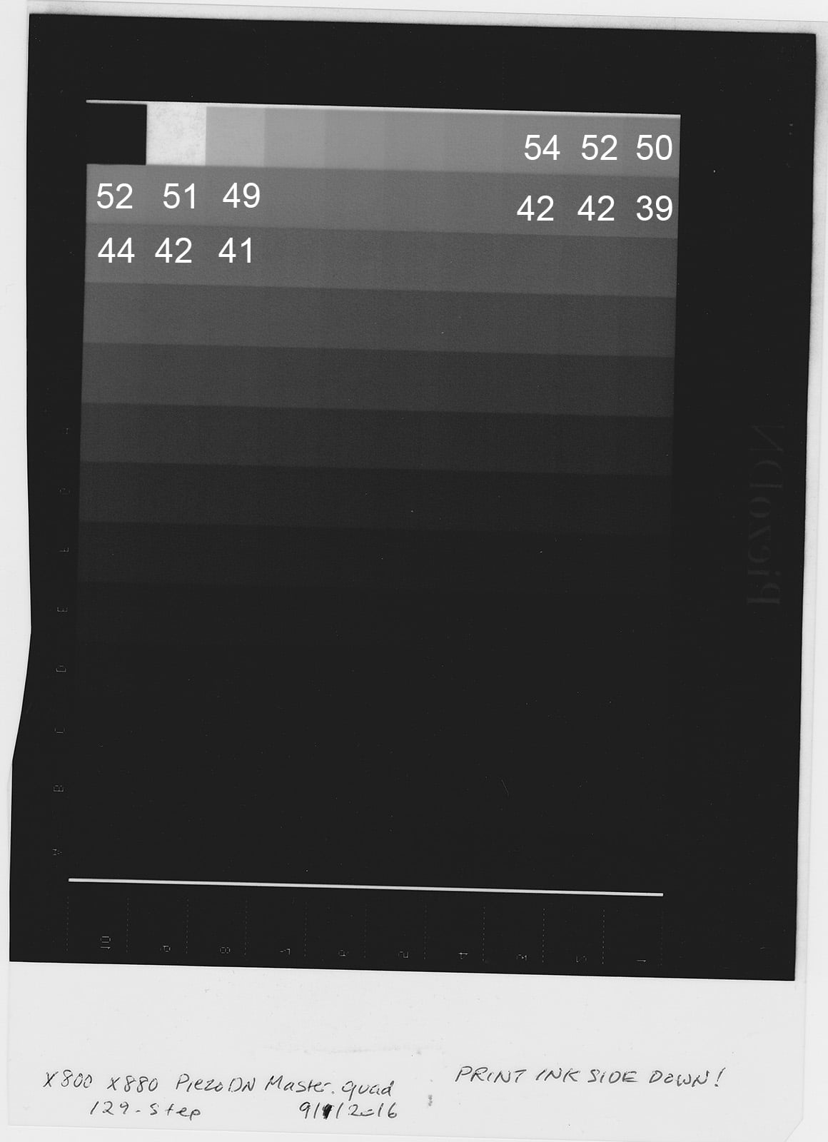
So, I went back and looked at the data from the print using the original master curve. I could see reversals in the data, and I noticed that they occurred from one column to the next. For example, if I look at the print, A10 should be lighter than B1, B10 should be lighter than C1, etc. But it’s not. Not to mention some reversals in the middle of the columns as well.
I started to suspect light fall-off in my vacuum printer unit, and perhaps uneven coating as the culprit. So, I printed another 129-step target using the negative from the x800-x880-PiezoDN-Master.quad curve. This time, I also rotated the target 90 degrees in the vacuum printer. The data looked similar to my first print, so I felt I could rule out light fall-off and uneven coating as the cause.
So, I turned to the negative itself. I don’t have a transmission densitometer, so I scanned it with a flatbed scanner. I opened the image in Photoshop and read the L/K values. They showed the same behavior I am seeing in the prints. Which leads me to believe that the reversals are coming from the negative itself, and not light fall-off or uneven coating.
If it’s coming from the negatives, then I believe it must be coming from the x800-x880-PiezoDN-Master.quad curve. Linearizing the curve didn’t help.
As a side note, I used the smoother tool to linearize a .quad file for piezography, and it worked beautifully. So I feel fairly confident that I know how to use the tools, and that the inks in my 3880 are fine.
Attached is the linearization curve from data printed using the the x800-x880-PiezoDN-Master.quad file. Any thoughts?
FYI, it’s not the master curve. I only changed about 2% of the curve (in the max densities) and I and other people have been printing successfully from it for months now. Something else is fishy.
You scanned this in reflective mode and not transparency mode and the scanner is not properly white balanced. That said, in the patches that can be read (lowest density to about 1/3 of the way down) I read linear results in photoshop.
I suggest scanning this properly, however, my own recent validation of a target printed with the more-dense master shows that it’s linear.
Did you just not install the linearized curve? In order to install a new curve, you have to run the printer install command (or package) again.
[attachment file=1339]
I’m uploading the image again, this time with selected measured L values from within Photoshop. What I see is that the L values reverse as you move from the end of one row down to the start of the next.
As a test, I tried printing the 129-step onto paper, and saw similar reversals. Furthermore, I went back to the ones I did for piezography, and observed the same pattern. However, the reversals were much smaller, so it wasn’t seen as a problem.
This is a printed out process after all. There will be significantly more ink in the highlights all the way through the light mid-tones and that’s what it looks like in the curves.